Download
1 / 25
250 likes | 423 Views
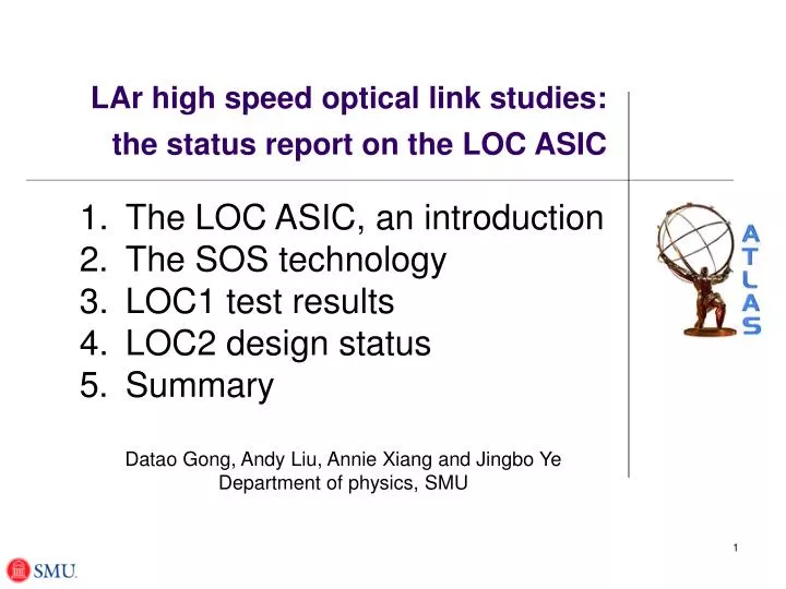
LAr high speed optical link studies: the status report on the LOC ASIC. The LOC ASIC, an introduction The SOS technology LOC1 test results LOC2 design status Summary Datao Gong, Andy Liu, Annie Xiang and Jingbo Ye Department of physics, SMU. The LOC ASIC, an introduction.

E N D
LAr high speed optical link studies: the status report on the LOC ASIC The LOC ASIC, an introduction The SOS technology LOC1 test results LOC2 design status Summary Datao Gong, Andy Liu, Annie Xiang and Jingbo Ye Department of physics, SMU
The LOC ASIC, an introduction • The LOC (link-on-chip) was proposed as a serializer ASIC for the ATLAS LAr readout upgrade, under the US-ATLAS upgrade program. • The initial idea was to integrate “everything” into one chip, including the optical interface. Fiber would be coupled directly to the chip to spare high speed copper traces on the PCB. • The project started with the SOS technology evaluation in 2006. • A first prototype, LOC1 was designed with collaborative effort between the EE and physics departments at SMU 2007. This prototype provided valuable information on key components, especially the PLL and the serializer structure, for the LOC2 design. • The second prototype, LOC2 is being designed as a 5 Gbps serializer ASIC. This design takes advantage of the CERN common project, the Versatile Link, and uses it as its optical interface. The submission is April 2009. • The whole project benefits tremendously from the CERN GOL ASIC design. We would like to express our gratefulness to many people in the CERN microelectronics group, especially to Paulo Moreira for his very kind help in the LOC project. Status Report on the LOC ASIC at LAr-Tile-L1Calo upgrade workshop, 11.14.08, CERN
The SOS technology 0.2 1.0×10⁻⁵ ΔVTH 0.1 5.0×10⁻⁶ • A 0.25 micron Silicon on Sapphire commercial CMOS technology has been chosen for the LOC ASIC development. • A dedicated test chip with transistors, ring oscillators and shift registers has been designed and fabricated for irradiation tests. • Some results from the irradiation tests have been published at RADECS 2007. • The TID test results on transistors are summarized here. The substrate is grounded. • Almost no leakage current change; • A small threshold voltage change happens at the very beginning of the irradiation and then remains unchanged with the increase of total dose. • The technology evaluation continues with more detailed studies, supported by the ADR (US DOE) program. ΔILEAK(A) ΔVTH(V) ΔILEAK NMOS 0.2 1.0×10⁻⁵ 0.1 5.0×10⁻⁶ PMOS Status Report on the LOC ASIC at LAr-Tile-L1Calo upgrade workshop, 11.14.08, CERN
The LOC1 test results 5:1 DFF based serializer 2:1 mux 16 bit data 5:1 DFF based serializer 8B/10B encoder 2:1 mux Solid line box: implemented; dashed line box: implemented in FPGA. 5:1 DFF based serializer 2:1 mux Ref. clk PLL + clock unit 5:1 DFF based serializer Control + configuration Current driver to VCSEL to VCSEL Output driver CML signal CML driver Eye diagram of an 27-1 pseudo random input data. The data rate is 2.5 Gbps. Large DJ is observed, understood and will be corrected in LOC2 The bit error rate bathtub curve at 2.5 Gbps, the best BER reached is ~10-11. Status Report on the LOC ASIC at LAr-Tile-L1Calo upgrade workshop, 11.14.08, CERN
Interface: Input buffer + 64B/66B + scrambler or 8B/10B + output buffer user data 16 5 Gbps LOC: 16:1 serialization CML output fiber Versatile Link clk system clk LOC2 Block diagram and design considerations • After many discussions with people in ATLAS Inner Tracker and LAr, and with more experience of the SOS technology, we now design the LOC2 ASIC in two parts: the 5 Gbps 16:1 serializer and the user interface. • Since the speed of the serializer has been pushed higher and higher, towards the technology limit, a 16:1 structure simplifies the implementation of the high speed circuits. • We move the framing unit into the interface part for better integration with both ATLAS Tracker and LAr readout systems. • We take advantage of the CERN common project, the Versatile Link, and move the optical interface into the VL, so LOC will only provide a CML electrical output. Config/control The LOC2 prototype aim for 2009.4 submission Status Report on the LOC ASIC at LAr-Tile-L1Calo upgrade workshop, 11.14.08, CERN
Interface to different users • For ATLAS Tracker, the input to the optical link may contain DC balance coding that may need to be removed to save on bandwidth overhead. • For LAr, link bandwidth is the premium. • We propose the interface chip/function block to be: user data 16 Input buffer: Extract user data and change width to 64B or 8B 64B/66B + scrambler or 8B/10B Output buffer: Change data to 16B, LVDS clk Low speed PLL + clock fan-out system clk Divided by N Status Report on the LOC ASIC at LAr-Tile-L1Calo upgrade workshop, 11.14.08, CERN
LVDS-To-CMOS CML Driver 5Gbps 16bit LVDS D flip-flop 312.5M 625M 2.5G 1.25G 312.5MHz Ref Clk 2:1MUX 2.5GHz PLL + clock fan-out The 16:1 serializer at 5 Gbps • The serializer is based on a cascade of 2:1 multiplexing units with only the last stage • working at 2.5 GHz clock. The logic structure is much simpler than the traditional shift • register based (20:1) serializer in which all registers work at 2.5 GHz clock. • The Critical components are: • The 2.5 GHz PLL with low jitter and a 50% duty cycle output. • The static D-flip-flop (chosen for SEE immunity) and the 2:1 MUX. The last stage is specially designed to work with the CML driver. • The CML driver. • We have finished schematics level simulations. Layout and simulations are in progress. Status Report on the LOC ASIC at LAr-Tile-L1Calo upgrade workshop, 11.14.08, CERN
LOC2 design status • Speed comparison of 0.25 μm SOS and BulkCMOS (TSMC) with inverter, and adjust the PMOS/NMOS transistors ratio for the same 01 and 10 transition time. done. • Choose a static D-flip-flop design that meets the 5 Gbps speed requirement. done. • Complete schematic level study on the 16:1 serializer. in progress. • Layout and verification of the 16:1 serializer. in progress. • Interface. may need help in manpower or postpone it into FPGA for the moment. Status Report on the LOC ASIC at LAr-Tile-L1Calo upgrade workshop, 11.14.08, CERN
Summary • The LOC ASIC proposal evolves with time. We incorporate into our LOC design the development from the Versatile Link project and decide to move the optical interface from the LOC to the V.Link. The LOC now is a 16:1 serializer plus user interface. Different interface ASICs or function blocks will be developed according to the application of the LOC. • Technology evaluation on the 0.25 micron SOS technology produced encouraging positive results and enables us to go ahead with the LOC design using this technology. More studies will be performed on this technology with support from the ADR program. • The design work for the present prototype, LOC2, is in progress. Simulation on critical components indicate that 5 Gbps serial data rate is hopeful. • We aim for the April 09 submission, and the tests in lab July 09. We will provide demo-link and system design document for groups that are interested in using this chip in the fall of 2009. Status Report on the LOC ASIC at LAr-Tile-L1Calo upgrade workshop, 11.14.08, CERN
Backup slides Status Report on the LOC ASIC at LAr-Tile-L1Calo upgrade workshop, 11.14.08, CERN
The inverter • PMOS/NMOS ratio adjusted to have the same 10 and 01 delays. The ratio is: n*(1.9/1.4) where n = 1,2,3,4… • Basic layout, multi-finer layout checked to optimize speed. The delay is about 32~35 ps (drive itself), corresponding to a frequency of about 30 GHz. Agree with the manufacturer's tech notes, and comparable with speeds achieved in 0.13 to 0.15 micron bulk CMOS technology. • A comparison is made with 0.25 micron bulk CMOS (TSMC) on the same inverter design. Simulation shows a 60 ps delay with the same layout and driving condition. schematics layout . Status Report on the LOC ASIC at LAr-Tile-L1Calo upgrade workshop, 11.14.08, CERN
The D-flip-flop (DFF) • We started out with the C2MOS type of DFF used in GOL, but moved to the TGDFF: ~20% faster, and at least the same SEE immunity (Ramanarayanan, Upenn). • Different transistor size, single finger and multi-finger layouts are checked. The total delay is 292 ps (slowest or the S-S corner). This indicates a 5 Gbps serializer possible, because the time needed for a basic unit (DFF+mux) is 400 ps. Mostly single-finger layout multi-finger layout schematics Status Report on the LOC ASIC at LAr-Tile-L1Calo upgrade workshop, 11.14.08, CERN
Test results on LOC1 • The in-lab tests: • Electric output: rise/fall times, amplitude. • Eye diagram. • Understand the jitter. • Bit error rate. • SEE with 200 MeV proton • Future tests planned on LOC1 Status Report on the LOC ASIC at LAr-Tile-L1Calo upgrade workshop, 11.14.08, CERN
LOC1 block diagram Ref. clk Control + configuration PLL + clock unit • Five function blocks: the input 8B/10B encoders, the 20:1 serializer, the output driver, the PLL and clock unit, and the control and configuration. • Solid line box: implemented; dashed line box: not implemented. • Loc1 is the 1st prototype only good for tests in lab. 5:1 DFF based serializer Input 2:1 mux 8B/10B encoder 16 bit data 5:1 DFF based serializer 2:1 mux 5:1 DFF based serializer 8B/10B encoder 2:1 mux 5:1 DFF based serializer to VCSEL Current driver to VCSEL Output driver CML signal CML driver Output Status Report on the LOC ASIC at LAr-Tile-L1Calo upgrade workshop, 11.14.08, CERN
LOC1 basic electrical characteristics • Input power supply: 2.5V (Analog/Digital), 3.3V VCSEL • Power consumption (with current configuration) ~200mW. • Input data signals LVCMOS 2.5V Reference clock 62.5MHz 20bit 8B/10B encoded input data Status Report on the LOC ASIC at LAr-Tile-L1Calo upgrade workshop, 11.14.08, CERN
Data Clock distribution LVDS Driver Board LVDS Interface Board LOC1 Carrier Board Clock FPGA: PRBS generator 8B/10B encoder Error detection Electrical Differential Test point Data TLK Interface Board TLK Carrier Board LVDS Receiver Board I/O to PC FPGA Board Clock LOC1 test system diagram • Tektronix 20GHz real-time oscilloscope (DSA72004) and Anritsu 12G BERT are used in the tests. • The VCSEL driver is not functioning. All tests are carried out through the CML driver on electrical signals only. • Tests performed at the test point (see figure) are the CML signal amplitude, the rise and fall times, and the jitter measurement and analysis. • The Bit Error Rate (BER) is measured with the Anritsu BERT. Status Report on the LOC ASIC at LAr-Tile-L1Calo upgrade workshop, 11.14.08, CERN
The rise and fall times and the amplitude • The logic in the digital part, and the PLL + clock unit are functioning as designed. The output serial bits are correct, checked on the scope. • The differential signal amplitude is about 240mV, measured by a differential probe. This is much lower than the 400 mV design spec. • The rise and fall times are data pattern dependent. They are measured to be around 150ps. This is boarder line for 2.5 Gbps signal. • The reason for the above problems are not completely known. The whole driver design will be abandoned. We will use a new driver design in LOC2. Comma (k28.5) code on differential electrical channel Status Report on the LOC ASIC at LAr-Tile-L1Calo upgrade workshop, 11.14.08, CERN
Eye diagram • An eye diagram is measured. • There is huge jitter generated inside LOC1. • Careful measurements were carried out to identify the components as well as possible sources of this jitter. • We think that we understand this problem very thoroughly. The huge DJ comes from the 4-arm 2-stage mux serializer design. This architecture is not necessary. New serializer design will be implemented in LOC2 to address this problem. • The RJ comes mostly from the PLL. Efforts are spent to improve the PLL design for LOC2. Eye diagram of the Input 27-1 Pseudo random data. UI = 400ps, for 2.5 Gbps. Status Report on the LOC ASIC at LAr-Tile-L1Calo upgrade workshop, 11.14.08, CERN
Jitter measurement method • DSA72004 employs the software package TDSJIT3 for jitter analysis. • Sample is recorded at 40ps and up to 50M data points in one data file — a snapshot of 2ms waveform length, for long term jitter analysis. • Algorithm performed in the frequency domain. • RJ and DJ components are extracted. Status Report on the LOC ASIC at LAr-Tile-L1Calo upgrade workshop, 11.14.08, CERN
Jitter measurement with TDSJIT3 • Jitter spectrum • Results on jitter in the serial data bit stream: • RJ_rms = 10ps, DJ_pk-pk = 230ps. • Out of the 230 ps DJ, the periodic jitter contributed by the serializer structure is175ps. This can be eliminated in LOC2. • Total jitter (@10-12 BER) = 310ps. Reminder: UI = 400ps. Status Report on the LOC ASIC at LAr-Tile-L1Calo upgrade workshop, 11.14.08, CERN
The Periodic jitter • A large periodic jitter is observed. • This strong data depending, n×492KHz jitter structure (2.5GHz/127/40 = 492KHz) is a clear indication that the jitter comes from an unmatched 4-arm 2-stage serializer. • New serializer structure will be implemented in LOC2 to address this problem. Status Report on the LOC ASIC at LAr-Tile-L1Calo upgrade workshop, 11.14.08, CERN
BERT signal generator FPGA board 62.5MHz 2.5GHz 62.5MHz 20bit Data BERT Error Detect LOC1 Serialized Data BER Bit error rate measurement The input amplitude is 110mV because of the Differential to single-ended converter. The BER measurement system We use the Anritsu MP1763/1764 BER Tester for this test Status Report on the LOC ASIC at LAr-Tile-L1Calo upgrade workshop, 11.14.08, CERN
The BER bathtub curve The bathtub curve at 2.5Gbps, the best BER reached is ~10-11. • The bathtub curve is obtained by shifting the reference clock with respect to the parallel data. • From this curve we extract: DJ_pk-pk = 235ps, RJ_rms =18ps, and total jitter = 478ps (@10-12 BER) • The low signal amplitude might cause the large RJ measurement: The BERT error detect requires 250 mV amplitude input, but our input is 240mV/2 ~ 110mV. Status Report on the LOC ASIC at LAr-Tile-L1Calo upgrade workshop, 11.14.08, CERN
LOC1 SEE test with 200 MeV proton (very preliminary) • LOC1+TLK2500 link operates at 2.5 Gbps with the LOC1 exposed in 200 MeV proton beam. • Flux: 5×10⁶ p/cm2/sec. Error free for 30 minutes, a fluence of 9×10⁹ p/cm2. After that TID effect may kicked in. Data analysis is on-going and more tests will be needed. • SEE cross section less than 1×10⁻¹⁰ cm2/proton. Or less than 1 error per link every hour at SLHC. Status Report on the LOC ASIC at LAr-Tile-L1Calo upgrade workshop, 11.14.08, CERN
Previous LOC2 block diagram Cntrl/Config Cntrl config Clk_ref PLL + clks 27-1 PRBS 8B/10B Comma MUX Input Data 16 bit Input register LVDS to LVCMOS 2:1 MUX to 8 bit 16 LVDS 10 bit Even bits shift register CML driver Serial output to Versatile Link 2:1 MUX Odd bits shift register Latch Output The preliminary LOC2 block diagram Parallel data Parallel data LOC VL fiber GBTx VL fiber System implementation Status Report on the LOC ASIC at LAr-Tile-L1Calo upgrade workshop, 11.14.08, CERN