Download
1 / 5
50 likes | 103 Views
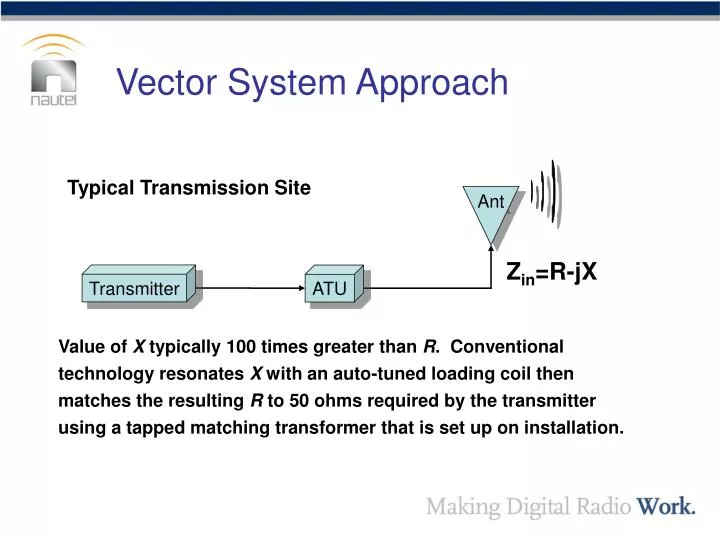
Vector System Approach. Typical Transmission Site. Ant. Z in =R-jX. Transmitter. ATU.

E N D
Vector System Approach Typical Transmission Site Ant Zin=R-jX Transmitter ATU Value of X typically 100 times greater than R. Conventional technology resonates X with an auto-tuned loading coil then matches the resulting R to 50 ohms required by the transmitter using a tapped matching transformer that is set up on installation.
Vector System Approach Environmental Effects Rain, fog, ice, snow and pollution can change the electrical characteristics of the antenna system Ant Zin=R-jX Transmitter ATU • Input impedance changes R ±50% X ±5% causing VSWR and change of antenna efficiency.
Vector System Approach Conventional System Response System effectiveness is dramatically affected. Ant P Zin=R-jX Transmitter ATU • Auto tuning mitigates variation of X. Change of R causes two detrimental effects: • High VSWR – Transmitter lowers its output power to reduce resulting reflected power. In extreme cases, transmitter may even shut down. • Change of Antenna Efficiency – Even if transmitter power were maintained constant, the variation of antenna efficiency would cause variation of radiated power. A 50% increase in R requires a 50% increase in transmitter power.
Vector System Approach Vector ATU Response to Impedance Change The effect on the system is reduced. Ant P Z Transmitter The Vector ATU automatically adapts to the new antenna impedance. Reflected Power maintained at near 0w.
Vector System Approach Vector Transmitter Response to Change of Antenna Efficiency Feedback signal adjusts TX output power to maintain constant antenna current. Antenna current is monitored. RS485 Link Ant P i Z