Download
1 / 15
150 likes | 275 Views
Project performed by:. Naor Huri Idan Shmuel. Project supervised by:. Ina Rivkin. Technion – Israel Institute of Technology Department of Electrical Engineering High Speed Digital Systems Lab. Spring 2007. Part A Presentation. multi processor system- two semesters project. Background.

E N D
Project performed by: Naor Huri Idan Shmuel Project supervised by: Ina Rivkin Technion – Israel Institute of Technology Department of Electrical Engineering High Speed Digital Systems Lab Spring 2007 Part A Presentation multi processor system- two semesters project
Background • This project is a part of a much larger project dealing with signal processing acceleration using hardware. In our project we will create a hardware acceleration to a given algorithm and analyze the advantages and disadvantages of such system, in comparison to a pure software implementation.
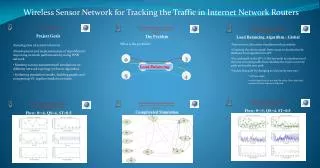
Problem • Running the signal processing algorithm takes too much time using a software on a standard PC Solution • A system designed especially for that target, using hardware accelerators and management unit
Ourproject • Creating an array of processors, each running the same program. • All processors are controlled by a switch. • The switch should be capable of receiving input vectors at a high rate, and sending each vector to an idle cpu for processing. • Input – an endless loop of incoming data packages, in random size. • Output – processed data, including vector histogram.
Data PackagesGenerator Block Diagram Gidel ProcStar FPGA switch On chip memory Processor I FIFO Board memory On chip memory Processor II FIFO Board memory On chip memory Processor N PCI BUS
The board • In this project we use the Gidel ProcStarII board. it contains a stratixII FPGA and 2 external DDRII. • The board connects to the PC through a PCI bus. This is an important feature that enables us to send packages from the PC to the board at a high rate.
what have we done so far? • An on chip system including a single NiosII CPU and an on chip memory. • This system’s creation flow will be described in the following slides
Step 1 - ProcWizard This tool from GIDEL generates the top level entity VHDL code for our project, after defining general parameters for our system, like clocks. It also provide the platform for the communication between the pc and the ProcStarII board via the PCI bus
Step 2 - inside Quartus- the SOPC Builder • After the GIDEL ProcWizard generates the VHDL code we need to add our component to the project. For that purpose we have the SOPC Builder: • In the SOPC Builder we have created a basic system that include a NiosII CPU, an on chip memory, leds and a jtag uart.
the SOPC Builder • We focus on a simple, small and power saving design, keeping in mind that these system of CPU and memory is one of many in the final system.
Step 3 – Quartus- synthesis • After connecting our component to the top level entity we are ready for synthesis. The Quartus generates a rbf file which is in turn used for loading the StratixII through the ProcWizard. • The synthesis summery is of much interest:
Analysis and synthesis • We can see for example that logic utilization is only 3% , and that we meet timing requirements
Step 4 – IDE- software and debugging • After loading the rbf file to the FPGA we use this tool to add a simple program to run on our cpu. It is compiled and then debugged using the jtag.
What’s next • Running the algorithm on a single NiosII. • Connecting our system to the PCI using Michael’s interface. • Designing the switch. • Implementing a full system with the switch controlling 2 niosII. • Expanding the above system, and testing the systems performance in order to find the optimal configuration.