Download
1 / 10
100 likes | 283 Views
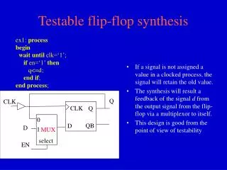
Q. CLK. CLK. Q. 0. QB. D. D. 1. MUX. select. EN. Testable flip-flop synthesis. ex1: process begin wait until clk=‘1’; if en=‘1’ then q<=d; end if ; end process ;. If a signal is not assigned a value in a clocked process, the signal will retain the old value.

E N D
Q CLK CLK Q 0 QB D D 1 MUX select EN Testable flip-flop synthesis ex1: process begin wait until clk=‘1’; if en=‘1’ then q<=d; end if; end process; • If a signal is not assigned a value in a clocked process, the signal will retain the old value. • The synthesis will result a feedback of the signal d from the output signal from the flip-flop via a multiplexor to itself. • This design is good from the point of view of testability
ENTITY cir IS PORT (D_in,EN,clk: IN BIT; Q,QB: OUT BIT); END cir; ARCHITECTURE bhv OF cir IS begin p1:process begin wait until clk='1'; if EN<='1' then end if; Q<=D_in; end process; end bhv;
ENTITY stm IS PORT (D_in,EN,clk: OUT BIT; Q,QB: IN BIT); END stm; ARCHITECTURE dtf OF stm IS BEGIN D_in <= '1' AFTER 0 ns, '1' AFTER 10 ns, '0' AFTER 20 ns, '1' AFTER 55 ns; EN <= '0' AFTER 0 ns, '1' AFTER 10 ns, '0' AFTER 20 ns, '0' AFTER 55 ns;
clk <= '0' AFTER 0 ns, '1' AFTER 10 ns, '0' AFTER 20 ns, '1' AFTER 30 ns, '0' AFTER 40 ns, '1' AFTER 50 ns, '0' AFTER 60 ns, '1' AFTER 70 ns, '0' AFTER 80 ns, '1' AFTER 90 ns; END dtf;
ENTITY stm IS PORT (D_in,En,clk: out BIT; Q,QB: in BIT); END stm; ARCHITECTURE dtf OF stm IS signal clk_EN_D: bit_vector(0 to 2); BEGIN clk_EN_D <= "010" after 0 ns, "101" after 10 ns, "010" after 20 ns, "100" after 30 ns, "000" after 40 ns, "110" after 50 ns, "001" after 55 ns, "001" after 60 ns, "111" after 70 ns, "011" after 80 ns,
"101" after 90 ns; clk <=clk_EN_D(0); EN <=clk_EN_D(1); D_in <=clk_EN_D(2); END dtf;
ENTITY bnc IS END bnc; use std.textio.all; ARCHITECTURE str OF bnc IS COMPONENT cir PORT (D_in,EN,clk: IN BIT; Q,QB: OUT BIT); END COMPONENT; COMPONENT stm PORT (D_in,EN,clk: OUT BIT; Q,QB: IN BIT); END COMPONENT; SIGNAL wD_in,wEN,wclk,wQ,wQB: BIT; for all: cir use entity work.cir (bhv); for all: stm use entity work.stm (dtf); -- Signals for the right order of the executions of the processes signal s,z:Boolean:=False; BEGIN circuit: cir PORT MAP(wD_in,wEN,wclk,wQ,wQB); generator: stm PORT MAP(wD_in,wEN,wclk,wQ,wQB);
-- Header of the results header: process variable dline1: line; variable dline2: line; constant L1: string:="This is the operation of the D-FlipFlop"; constant L2: string:=" TIME clk D_in EN Q QB "; begin write (dline1, L1, right, 1); writeline (output, dline1); write (dline2, L2, right, 1); writeline (output, dline2); s<=True; wait; end process;
-- Monitoring the result and printing them out monitor: process (wD_in,wEN,wclk,wQ,wQB) variable dline: line; begin if s=True and z=True then write (dline, NOW, right, 7); write (dline, wclk, right, 5); write (dline, wD_in, right, 6); write (dline, wEN, right, 8); write (dline, wQ, right, 10); write (dline, wQB, right, 8); writeline (output, dline); end if; end process;
-- This is a line, only Underline: process variable dline: line; constant L: string:="=============================================="; begin wait on s; write (dline, L, right, 1); writeline (output, dline); z<=True; end process; END str;