Download
1 / 20
210 likes | 590 Views
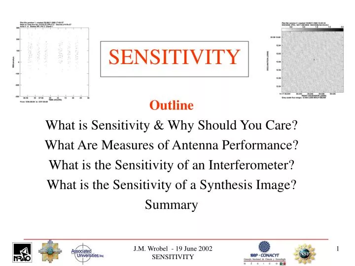
SENSITIVITY. Outline What is Sensitivity & Why Should You Care? What Are Measures of Antenna Performance? What is the Sensitivity of an Interferometer? What is the Sensitivity of a Synthesis Image? Summary. What is Sensitivity & Why Should You Care?

E N D
SENSITIVITY Outline What is Sensitivity & Why Should You Care? What Are Measures of Antenna Performance? What is the Sensitivity of an Interferometer? What is the Sensitivity of a Synthesis Image? Summary J.M. Wrobel - 19 June 2002 SENSITIVITY
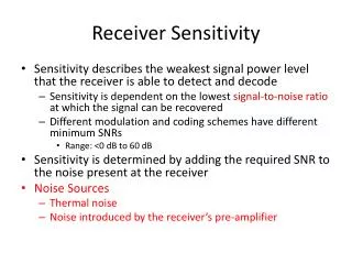
What is Sensitivity & Why Should You Care? Measure of weakest detectable radio emission Important throughout research program Technically sound observing proposal Sensible error analysis in publication Expressed in units involving Janskys Unit for interferometer is Jansky (Jy) Unit for synthesis image is Jy beam-1 1 Jy = 10-26 W m-2 Hz-1 = 10-23 erg s-1 cm-2 Hz-1 Common to use milliJy or microJy J.M. Wrobel - 19 June 2002 SENSITIVITY
Measures of Antenna Performance Source and System Temperatures What is received power P? Write P as equivalent temperature of matched termination at receiver input Rayleigh-Jeans limit to Planck law Boltzmann constant kB Observing bandwidth Amplify P by g2 where g is voltage gain Separate powers from source, system noise Source antenna temperature Ta => source power System temperature Tsys=> noise power J.M. Wrobel - 19 June 2002 SENSITIVITY
Measures of Antenna Performance Gain Source power Let for source flux density S, constant K Then (1) But source power also (2) Antenna area A, efficiency Receiver accepts 1/2 radiation from unpolarized source Equate (1), (2) and solve for K K is antenna’s gain or “sensitivity”, unit degree Jy-1 K measures antenna performance but no Tsys J.M. Wrobel - 19 June 2002 SENSITIVITY
Measures of Antenna Performance System Equivalent Flux Density Antenna temperature Source power Express system temperature analogously Let SEFD is system equivalent flux density, unit Jy System noise power SEFD measures overall antenna performance Depends on Tsys and Examples in Table 9-1 J.M. Wrobel - 19 June 2002 SENSITIVITY
Interferometer Sensitivity Real Correlator - 1 Simple correlator with single real output that is product of voltages from antennas j,i SEFDi = Tsysi / Ki and SEFDj = Tsysj / Kj Each antenna collects bandwidth Interferometer built from these antennas has Accumulation time , system efficiency Source, system noise powers imply sensitivity Weak source limit S << SEFDi S << SEFDj J.M. Wrobel - 19 June 2002 SENSITIVITY
Interferometer Sensitivity Real Correlator - 2 For SEFDi = SEFDj = SEFD drop subscripts Units Jy Interferometer system efficiency Accounts for electronics, digital losses Eg: VLA continuum Digitize in 3 levels, collect data 96.2% of time Effective J.M. Wrobel - 19 June 2002 SENSITIVITY
Interferometer Sensitivity Complex Correlator Delivers two channels Real SR , sensitivity Imaginary SI , sensitivity Eg: VLBA continuum Figure 9-1 at 8.4 GHz Observed scatter SR(t), SI(t) Predicted = 69 milliJy Resembles observed scatter J.M. Wrobel - 19 June 2002 SENSITIVITY
Interferometer Sensitivity Measured Amplitude Measured visibility amplitude Standard deviation (sd) of SRor SIis True visibility amplitude S Probability Figure 9-2 Behavior with true S / High: Gaussian, sd Zero: Rayleigh, sd Low: Rice. Sm gives biased estimate of S. Use unbias method. J.M. Wrobel - 19 June 2002 SENSITIVITY
Interferometer Sensitivity Measured Phase Measured visibility phase True visibility phase Probability Figure 9-2 Behavior with true S / High: Gaussian Zero: Uniform Seek weak detection in phase, not amplitude J.M. Wrobel - 19 June 2002 SENSITIVITY
Image Sensitivity Single Polarization Simplest weighting case where visibility samples Have same interferometer sensitivities Have same signal-to-noise ratios w Combined with natural weight (W=1), no taper (T=1) Image sensitivity is sd of mean of L samples, each with sd , ie, No. of interferometers No. of accumulation times So J.M. Wrobel - 19 June 2002 SENSITIVITY
Image Sensitivity Dual Polarizations - 1 Single-polarization image sensitivity Dual-polarization data => image Stokes I,Q,U,V Gaussian noise in each image Mean zero, Polarized flux density Rayleigh noise, sd Cf. visibility amplitude, Figure 9-2 Polarization position angle Uniform noise between Cf. visibility phase, Figure 9-2, J.M. Wrobel - 19 June 2002 SENSITIVITY
Image Sensitivity Dual Polarizations – 2 Eg: VLBA continuum Figure 9-3 at 8.4 GHz Observed T: Stokes I, simplest weighting B: Gaussian noise = 90 microJy beam-1 Predicted Previous eg Plus here L = 77,200 So = 88 microJy beam-1 J.M. Wrobel - 19 June 2002 SENSITIVITY
Image Sensitivity Dual Polarizations – 3 Eg: VLBA continuum Figure 9-3 at 8.4 GHz Observed T: Ipeak = 2 milliJy beam-1 B: Gaussian noise = 90 microJy beam-1 Position error from sensitivity? Gaussian beam = 1.5 milliarcsec Then = 34 microarcsec Other position errors dominate J.M. Wrobel - 19 June 2002 SENSITIVITY
Image Sensitivity Dual Polarizations – 4 Eg: VLA continuum Figure 9-4 at 1.4 GHz Observed Q, U images, simplest weighting Gaussian = 17 microJy beam-1 Predicted = 16 microJy beam-1 J.M. Wrobel - 19 June 2002 SENSITIVITY
Image Sensitivity Dual Polarizations – 5 Eg: VLA continuum Figure 9-4 at 1.4 GHz Observed Q, U images, simplest weighting = 17 microJy beam-1 Form image of Rayleigh noise in P Sd 11 microJy beam-1 Predicted Sd Sd 11 microJy beam-1 J.M. Wrobel - 19 June 2002 SENSITIVITY
Image Sensitivity Dual Polarizations – 6 Eg: VLA continuum Figure 9-4 at 1.4 GHz Observed I, Q, U images, simplest weighting Gaussian noise I, Q, U will have same sd if each is limited by sensitivity Recall Other factors can increase Suspect dynamic range as Ipeak = 10,000 Lesson: Use sensitivity as tool to diagnose problems J.M. Wrobel - 19 June 2002 SENSITIVITY
Sensitivity Summary – 1 One antenna System temperature Tsys Gain K Overall antenna performance is measured by system equivalent flux density SEFD Units Jy J.M. Wrobel - 19 June 2002 SENSITIVITY
Sensitivity Summary - 2 Connect two antennas to form interferometer Antennas have same SEFD, observing bandwidth Interferometer system efficiency Interferometer accumulation time Sensitivity of interferometer Units Jy J.M. Wrobel - 19 June 2002 SENSITIVITY
Sensitivity Summary - 3 Connect N antennas to form array Antennas have same SEFD, observing bandwidth Array has system efficiency Array integrates for time tint Form synthesis image of single polarization Sensitivity of synthesis image Units Jy beam-1 J.M. Wrobel - 19 June 2002 SENSITIVITY