Download
1 / 44
440 likes | 535 Views
Advanced Information Systems Development (SD3043) Architectural Patterns and Model Driven Architecture (MDA). Learning Objectives. On completion of the lecture students should understand: The role of architectural patterns in information systems development

E N D
Advanced Information Systems Development (SD3043)Architectural Patterns and Model Driven Architecture (MDA)
Learning Objectives • On completion of the lecture students should understand: • The role of architectural patterns in information systems development • The notion of model driven architecture
Lecture Layout • Architectural Patterns • Model Driven Architecture • Concepts • Process
Software Architecture • ‘A software architecture is a description of the subsystems and components of a software system and the relationships between them. • Subsystems and components are typically specified in different views to show the relevant functional and non-functional properties of a software system. • The software architecture of a system is an artefact. It is the result of the software design activity.’ Buschmann et al. (1996)
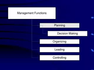
Architectural Aspectsof Software Design • Software architects undertake the following activities: • Subsystems and major components are identified • Any inherent concurrency is identified • Subsystems are allocated to processors • A data management strategy is selected • A strategy and standards for human–computer interaction are chosen
Architectural Patterns • The fundamental problem to be solved with a large system is how to break it into chunks manageable for human programmers to understand, implement, and maintain. • Large-scale patterns for this purpose are called architectural patterns. • Architectural patterns are related to design patterns, but higher level and larger scale. • For more details, see Buschmann et al. (1996), chapter 2
Architectural Pattern Examples • High level decompositions (support a controlled decomposition of an overall system into cooperating subtasks): • Layers • Distributed systems: • Multi-tier (e.g. 3-tier) • Broker • Interactive systems (support the structuring of software systems that feature human-computer interaction): • Model-view-controller • Presentation-Abstraction-Control:Pattern • Adaptable/reusable systems (support extension of applications and their adaptation to evolving technology and changing functional requirements): • Microkernel
Layers: Pattern The Layers pattern helps to structure applications that can be decomposed into groups of subtasks in which each group of subtasks is at a particular level of abstraction.
Layer 7: Application Provides miscellaneous protocols for common activities. Layer 6: Presentation Structures information and attaches semantics. Layer 5: Session Provides dialogue control and synchronization facilities. Layer 4: Transport Breaks messages into packets and ensures delivery. Layer 3: Network Selects a route from sender to receiver. Layer 2: Data Link Detects and corrects errors in bit sequences. Layer 1: Physical Transmits bits: sets transmission rate bit-code, connection, etc. OSI(Open Systems Interconnection) 7 Layer Model (Adapted from Buschmann et al., 1996) Each layer deals with a specific aspect of communication and uses the services of the next lower layer.
Layers: Issues • Issues that need to be addressed include: • Interfaces should be stable, and even be prescribed by standards body. • Late source code changes should not ripple the system. They should be confined to one component and not affect others. • Parts of the system should be exchangeable. Components should be able to be replaced by alternative implementations without affecting the rest of the system. • Complex components need further decomposition • Crossing component boundaries may impede performance, for example when a substantial amount of data must be transferred overall several boundaries, or where there are many boundaries to cross. • Each component should be coherent – if one component implements divergent issues its integrity may be lost.
Developing a Layered Architecture • Define the criteria by which the application will be grouped into layers. A commonly used criterion is level of abstraction from the hardware. • Determine the number of layers. • Name the layers and assign functionality to them. • Specify the services for each layer. • Refine the layering by iterating through steps 1 to 4.
Developing a Layered Architecture • Specify interfaces for each layer. • Specify the structure of each layer. This may involve partitioning within the layer. • Specify the communication between adjacent layers (this assumes that a closed layer architecture is intended). • Reduce the coupling between adjacent layers. This effectively means that each layer should be strongly encapsulated. (Adapted from Buschmann et al., 1996)
Layers: Advantages • Reuse of layers • Standardization of tasks and interfaces • Only local dependencies between layers • Programmers and users can ignore other layers • Different programming teams can handle each layer
Layers: Disadvantages • Cascades of changing behavior • Lower efficiency of data transfer • Difficult to choose granularity of layers • Difficult to understand entire system
Client/Server Architectural Pattern • Client / Server • One subsystem (server) provides services to instances of other subsystems (clients) • Information system with central database Client Client Server
Broker: Pattern • The Booker can be used to structure distributed software systems with decoupled components that interact by remote service invocations. • Communication is coordinated by a broker component which does things like forwarding requests and transmitting results and exceptions.
Broker: Problem • Building a complex software system as a set of decoupled and interoperating components, rather than as a monolithic application, results in greater flexibility, maintainability and changeability. • Independent components make the system distributable and scalable. • Components should be able to access services provided by others through remote, location-transparent invocations. • Adding, removing, activating, locating components possible at run time • The architecture should hide system- and implementation specific details from the users of components and services
Broker: Solution • Use brokers to mediate between clients and servers • Clients send requests to a broker • Brokers locate appropriate servers; forward requests; and relay results back to clients • May have client-side and/or server-side proxies
«component» Server 1 «component» Client A «component» Server 2 «component» Broker «component» Client B «component» Server 3 Schematic of Simplified Broker Architecture
Broker: Examples • CORBA: Common Object Request Broker Architecture – object oriented technology for distributing objects on heterogeneous systems. • World Wide Web – the largest available broker system. Browsers act as brokers and the WWW servers play the role of service providers. • Object Linking and Embedding (OLE) is a technology that allows embedding and linking to documents and other objects developed by Microsoft • Multi-agent systems are often coordinated through brokers such as JADE (Java Agent Development Framework ) that provide a standard mechanism for relaying messages, based on a high-level communication protocol. • Individual agents may be implemented in any language as long as they can input/output according to the protocol.
Broker: Advantages and Disadvantages • Advantages • Components can be developed independently • Location transparency • Components and broker easily adapted • Interoperability between different broker systems (if they understand a common protocol for exchange of massages) • Disadvantages • Low fault tolerance • Limited efficiency (high communications cost; introduces layers to enable it to be portable, flexible and changeable) • Difficult to test (many components involved)
Model View Controller http://java.sun.com/blueprints/patterns/MVC-detailed.html
Presentation-Abstraction-Control:Pattern • A system implemented as a hierarchy of cooperating agents. Each agent is responsible for a specific aspect of functionality, and consists of: • A presentation component responsible for its visible behaviour • An abstraction component which maintains the data model for the agent • A control component which determines the dynamics of agent operation and communication
P-A-C: Problem • Interactive system viewed as a set of cooperating agents, often developed independently • Some agents specialize in HCI; others maintain data; others deal with error handling, etc. • Each agent is specialised for a specific task, and all agents together provide the system functionality. • Changes to individual agents should not affect the whole system
P-A-C: Solution • Define top-level agent with core functionality and data model, to coordinate the other agents and (possibly) also coordinate user interaction • Define bottom-level agents for specific, primitive semantic concepts and/or services in the application domain • Connect top and bottom levels via intermediate agents which supply data to groups of lower level agents • For each agent separate core functionality from HCI
P-A-C: Example • Information system for political elections, with: – Spreadsheet for entering data – Various tables and charts for presenting current standings • Users interact through graphical interface but different versions exist for different user needs • Top-level agent holds data repository • Different bottom-level agents for different types of charting, analysis and error handling • Intermediate agent to coordinate views of system
P-A-C: Advantages • Separation of different concepts as individual agents that can be maintained separately. • Each agent maintains its own state and data, coordinated with, but independent of other PAC agents. Each PAC agent provides own HCI. This allows the development of a dedicated data model and user interface for each semantic concepts within application. • Changes to presentation or abstraction in an agent doesn’t affect other agents • Easy to integrate/replace agents • Suits multi-tasking • Suits multi-user applications
Disadvantages • Increased complexity: Can have too many, too simple bottom-level agents • Can be difficult to get control right while maintaining independence of agents • Long chains of communication may be inefficient: For example, if a bottom-level agent retrieves data from the top-level agent, all intermediate level agents along the path from the bottom to the top of the PAC hierarchy are involve din this data exchange.
Microkernel: Pattern • For systems which must be easily adaptable to changing requirements (e.g. changing versions of operating systems) • It separates minimal functional core from extended functionality and customer-specific parts. • It provides sockets in the microkernel for plugging in these extensions and coordinating them.
Microkernel: Problem • Software systems with long life spans must evolve as their environment evolves • Such systems must be adaptable to changes in existing platforms and must be portable to new platforms • There may be a large number of different but similar platforms • To conform with standards on different platforms it may be necessary to build emulators on top of the core functionality • Thus the core should be small separated into a component with minimal size, and services that consume as little processing power as possible.
Microkernel: Solution • Build a microkernel component which encapsulates all the fundamental services of your application • The microkernel: – Maintains system-wide resources (e.g. files) – Enables other components to communicate – Allows other components to access its functionality • External servers implement their own view of the microkernel, using the mechanisms available from the microkernel. Every external server is a separate process that itself represents an application platform. • Clients communicate with external servers using the communication facilities provided by the microkernel
Microkernel: Example • Operating system for desktop computers: • Must be portable to relevant hardware platforms and adapt as these evolve. • Must be able to run applications developed for other established operating systems – e.g., users could choose which OS from a menu. • Each of these OSs is built as an external server on top of the microkernel.
Microkernel: Advantages and Disadvantages • Advantages • Porting to a new environment normally doesn’t need changes to external servers or clients • Thus external servers or clients can be maintained independently of kernel • Can extend by adding new external servers • Can distribute the microkernel to several machines, increasing availability and fault tolerance • Disadvantages • Performance overhead in having multiple views of system • Complexity of design and implementation: May be difficult to predict which basic mechanisms should be in the microkernel
Model Driven Architecture • Main idea: separate the business and application logic of a system from the underlying platform technology. • The abstract view of what the system must do is PIM. • Generate platform-specific models (PSMs) from platform-independent models (PIMs) • PSM is then transformed to implementation code using automated tools. • A single PIM can be implemented • Reverse engineering – by transforming code into PIM and using to re-implement the system on a modern platform.
Promise of MDA • Facilitate the creation of machine-readable models with a long-term flexibility • Technology obsolescence: New implementation infrastructure can be more easily integrated and supported by existing designs. • Productivity and time-to-market: by automatic many development tasks, developers are freed up to focus their attention on the core logic of the system • Testing and simulation: models can be directly validated against requirements
Concepts of MDA • System • The context is the system either existing or under construction • Model • A model is a formal specification of the function, structure and behaviour of a system within a context and from a specific point of view • Model is usually represented in UML • Model Driven • Software development process where models are used as the primary source for documenting , analysing etc. a system
Concepts of MDA II • Architecture • Specification of the parts and connectors of the system and the rules for the interactions of the parts • Viewpoint • Abstraction technique for focusing on a particular part of the system isolating any irrelevant information • Can be represented by one or more models
MDA Viewpoints • Three Default viewpoints • Computation independent • Focuses on the context and requirements of the system without consideration of its structure or processing • Platform independent • Focuses on the operational capabilities of a system outside the context of a specific platform • Platform specific • Add details related to a specific platform
Concepts of MDA • Platform • Set of subsystems and technologies that provide a coherent set of functionality through interfaces and usage patterns (e.g. OS, DB) • Model Transformation • Process of converting one system to another within the same system • Implementation • Specification that provides all the information required to construct a system and to put it into operation
MDA Models • Computation Independent Model (CIM) • Business or domain model – vocabulary familiar to subject domain experts (SMEs) • Represents what the system is suppose to do • Hides information on system implementation • CIM requirements should be traceable to the other two models
MDA Models • Platform Independent Model (PIM) • Defines services in a general abstraction way • Ignores technical details • Platform Specific Model (PSM) • Combines PIM specification with details of particular a platform
MDA Process • Create a platform-independent model expressed via UML • Transform this model to a specific platform model (e.g. .NET, SOAP etc) Source Model + Transformation Rules = Target Model
Summary • Architectural patterns allow systems to be broken into chunks that can be developed (to some degree) and maintained independently • These patterns support large-scale, long-term development and maintenance
Web References • N.B. Harrison, P. Avgeriou, U. Zdun. Using Patterns to Capture Architectural Decisions. IEEE Software, July/August 2007 http://iwi.eldoc.ub.rug.nl/FILES/root/2007/IEEESoftwHarrison/2007IEEESoftwHarrison.pdf • M. Stal. Using Architectural Patterns and Blueprints for Service-Oriented Architecture. IEEE Software, March/April 2006, http://www.stal.de/Downloads/ieeesoa.pdf • Buschmann et al. (1996) Pattern oriented software architecture • Model Driven Architecture http://www.omg.org/mda/