Download
1 / 25
250 likes | 360 Views
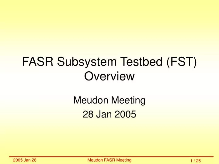
FASR Subsystem Testbed (FST) Overview. Meudon Meeting 28 Jan 2005. Overview of Project. Proposed Goals Hardware Overview Current Status Time-line / Schedule. Proposed Goals. RFI Mitigation

E N D
FASR Subsystem Testbed (FST)Overview Meudon Meeting 28 Jan 2005
Overview of Project • Proposed Goals • Hardware Overview • Current Status • Time-line / Schedule
Proposed Goals • RFI Mitigation • Interferometric and total power observations of terrestrial and satellite sources of radio interference • Characterization of interference levels relative to solar signal • Development of RFI mitigation strategies • Identify interference frequencies and blank/remove (determine optimum frequency resolution) • Identify intermittent interference and use frequency if okay, but blank if not • Produce “fast” algorithms that can work in real time
Proposed Goals • Calibration Strategies • Investigate the use of satellite beacons for calibration • Investigate methods of calibrating across band vs. integrated band—is the band calibration separable? • Support FASR correlator design task • Solar Observations • Observe type III and other dm bursts • Verify phase closure and measure centroid position as a function of time and frequency • Obtain type III trajectories, fragmentation
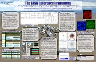
Front End Box Control Room Chassis Ctrl Rm PC Remote PC Hardware Overview System Block Diagram Colors denote different locations • blue = front end box (thermal control?) • orange = chassis in control room • yellow = PC in control room • green = remote PC
Storage PC • Two Raid-0 250 GB SATA disks (sustained transfer speed better than 40 MB/s) • 3.2 GHz CPU • 2 GB RAM • External 250 GB disk (for data transport?) • DVD+RW disk writer (for selected data transport) • CD-RW disk writer
Digitizer Acqiris DC271 + Cougar Chassis • Tests show excellent performance: • Phase jitter (time synchronization, 30 ps) • Triggered acquisition (segments) • Sustained transfer speed (74 MB/s) • Retrigger time (700 ns) • Aliasing characteristics
Image Rejection Spectral Line Downconverter
Block Downconverter 1-5 GHz 1-5 GHz IF to spectral line downconverter 1-9 GHz RF from optical receiver 9-5 GHz Same design as for CARMA—mechanical design for chassis exists. Need three of items in box, one of items for LO Control Item: switch (1-5 vs. 9-5 GHz bands)
Optical Link Same design as for CARMA—Photon Systems Inc already agreed to make them for us. Plan to set one up in lab for end-to-end test Control Item: PAM (post-amplifier module) Monitor Items
Current Status • Lab at NJIT has been developed for setup and test of hardware design. • Digitizer and PC are available for testing. All tests so far are very encouraging. LabView software for acquisition, quick look, and playback have been developed. • Spectral line downconverter not yet available, but similar one is available for testing of setup and procedures. • Block downconverter is understood to part level, but not yet purchased and tested. • Optical link will be ATA 11 GHz link (also used for CARMA)—provided by PSI. Details yet to be worked out. • PAM (post-amplifier module) appears to be needed. Cost and complexity of operation are unknown. • Mechanical design as yet completely undeveloped. CARMA mechanical design is available as a guide. • Control software not yet developed. CARMA software is available as a guide.
Time-Line / Schedule NJIT: 2005 Feb: CARMA board testing begins 2005 Apr: PAM module and optical link assembled, Spectral line downconverter obtained. 2005 July: NJIT hardware mockup complete 2005 Aug: Control system functional at NJIT 2005 Sep: Hardware mechanical design complete 2005 Nov: Parts obtained for two additional channels 2005 Dec: Hardware shipped to OVRO Berkeley: 2005 Feb: Draft data format 2005 May: Software correlator (IDL code) functional at basic level, working on NJIT test data 2005 July: Data format complete 2005 Sep: Definition of software correlator “plug-in” modules begun 2006 Mar: Software correlator “plug-in” modules ready for testing
Time Line / Schedule (cont’d) Maryland: 2005 Apr: Observing / Acquisition sequence definition for various modes (terrestrial RFI, satellite RFI, satellite calibration, solar+RFI, solar bursts) 2005 Jun: Strategies for characterization of RFI from data 2005 Aug: Begin exploring amp/phase data from NJIT (test inputs) OVRO: 2005 May: Trenching begins at OVRO 2005 July: Optical cable and racks / dog boxes for equipment installed at OVRO 2005 Dec: Hardware installed at OVRO—testing begins 2006 Jan: Satellite data taken for calibration / phase closure demo 2006 Jan: Solar / RFI data taking begins Caltech: 2005 Feb: Software for controlling CARMA board 2005 May: Spectral line downconverter 2005 Jun: Software for controlling spectral line downconverter 2005 Nov: 3 additional downconverters plus hardware chassis
FOCIS FASR Offline Correlator Implemented in Software
FOCIS Philosophy FOCIS plays the roll of all the hardware and software between the digitized IF and the interim database. • This implies what FOCIS should do. • It also implies what tasks are outside its scope.
FOCIS Inputs • Primary input data: • Data sample files generated by NJIT acquisition system • OR Simulated data files generated by UCB software • Metadata file to support identification of appropriate input file • CLI-specified analysis parameters • Future option: (Simulated) RFI and calibration database files • Otherwise, all input ancillary parameters required for analysis should be included in the data sample files. • Each independent execution analyzes a single scan (or part thereof). • FOCIS has no knowledge of overall objective of scan.
FOCIS Outputs • Primary output is semi-calibrated visibility files that mimic the interim database. • Output displays will mimic the role of possible realtime correlator displays. • Additional displays and analysis will be limited to features that directly support debugging or prompt evaluation of output. • It is assumed that analysis of the FOCIS output files uses software developed elsewhere (Umd?)
FOCIS Implementation • Optimized for transparency and flexibility in analysis options. • Not necessarily optimized for speed. • IDL-coded using ssw support as needed. • Developed to run on normally configured Windows PC’s (expected, but not guaranteed to also run on Unix workstations)
Correlator Flow Diagram? Downsampling? E.g. 3 bit From other channel Correlation Delay Adjustments FFT or Polyphase Filter Complex Gain Adjustments RFI Database RFI Flagging Averaging / Accumulation Frequency Averaging