Download
1 / 10
100 likes | 212 Views
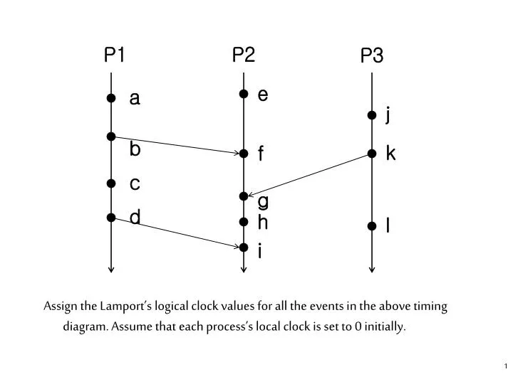
P1. P2. P3. e. a. j. b. k. f. c. g. d. h. l. i. Assign the Lamport’s logical clock values for all the events in the above timing diagram. Assume that each process’s local clock is set to 0 initially. P1. P2. P3. e. 1. a. 1. j. 1. 2. b. 2. k. f. 3. c. 3. 4. g. d.

E N D
P1 P2 P3 e a j b k f c g d h l i • Assign the Lamport’s logical clock values for all the events in the above timing diagram. Assume that each process’s local clock is set to 0 initially.
P1 P2 P3 e 1 a 1 j 1 2 b 2 k f 3 c 3 4 g d 4 h 5 l 3 i 6 • From the above timing diagram, what can you say about the following events? • between a and b: a b • between b and f : b f • between e and k: concurrent • between c and h: concurrent • between k and h: k h
/ • Fidge’s Logical Clocks • with Lamport’s clocks, one cannot directly compare the timestamps of two events to determine their precedence relationship - if C(a) < C(b) then a b - if C(a) < C(b), it could be a b or a b - e.g, events e and b in Figure previous page * C(e) = 1 and C(b) = 2 * thus C(e) < C(b) but e b • the main problem is that a simple integer clock can not order both events within a process and events in different processes • C. Fidge developed an algorithm that overcomes this problem • Fidge’s clock is represented as a vector [c1 , c 2 , …, cn] with an integer clock value for each process (cicontains the clock value of process i). / / /
Fidge’s Algorithm • The Fidge’s logical clock is maintained as follows: • FLC1: Initially all clock values are set to the smallest value. • FLC2: The local clock value is incremented at least once before each primitive event in a process. • FLC3: The current value of the entire logical clock vector is delivered to the receiver for every outgoing message. • FLC4: Values in the timestamp vectors are never decremented. • FLC5: Upon receiving a message, the receiver sets the value of each entry in its local timestamp vector to the maximum of the two corresponding values in the local vector and in the remote vector received. The element corresponding to the sender is a special case; it is set to one greater than the value received, but only if the local value is not greater than that received.
Get r_vector from the received msg sent by process q; if l_vector [q] r_vector[q] then l_vector[q] : = r_vector[q] + 1; for i : = 1 to n do l_vector[i] := max(l_vector[i], r_vector[i]); • Timestamps attached to the events are compared as follows: • ep fq iff Tep [p] < Tfq [p] • (where ep represents an event e occurring in process p, Tep represents the timestamp vector of the event ep , and the ith element of Tep is denoted by Tep [i].) • This means event ep happened before event fq if and only if process q received a direct or indirect message from p and that message was sent after ep had occurred. If ep and fq are in the same process (i,e., p = q), the local elements of their timestamps represent their occurrences in the process.
P1 P2 P3 e a j b k f c g d h l i • Assign the Lamport’s and Fidge’s logical clock values for all the events in the above timing diagram. Assume that each process’s logical clock is set to 0 initially.
P1 P2 P3 e [1,0,0] 1 a [0,1,0] 1 j 1 [0,0,1] 2 [2,0,0] b 2 k f [3,2,0] [0,0,2] 3 c [3,0,0] 3 [3,3,3] 4 g d [4,0,0] 4 h 5 [3,4,3] l 3 [0,0,3] i 6 [5,5,3]
The above diagram shows both Lamport timestamps (an integer value ) and Fidge timestamps (a vector of integer values ) for each event. • Lamport clocks: 2 < 5 since b h, 3 < 4 but c g. • Fidge Clocks: f h since 2 < 4 is true, b h since 2 < 3 is true, h a since 4 < 0 is false, c h since (3 < 3) is false and ( 4<0) is false.
P1 P2 P4 P3 a e j m b k f c n g d h o l i • Assign the Lamport’s and Fidge’s logical clock values for all the events in the above timing diagram.
READING Reference: • Colin Fidge, “Logical Time in Distributed computing systems”, IEEE Computer, Vol. 24, No. 8, pp. 28-33, August 1991.