Download
1 / 74
750 likes | 938 Views
ELECTRICAL CIRCUITS. The CELL. The cell stores chemical energy and transfers it to electrical energy when a circuit is connected. When two or more cells are connected together we call this a Battery. The cells chemical energy is used up pushing a current round a circuit.

E N D
The CELL The cell stores chemical energy and transfers it to electrical energy when a circuit is connected. When two or more cells are connected together we call this a Battery. The cells chemical energy is used up pushing a current round a circuit.
What is an electric current? An electric current is a flow of microscopic particles called electrons flowing through wires and components. - + In which direction does the current flow? from the Negative terminal to the Positive terminal of a cell.
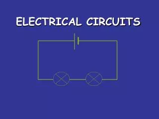
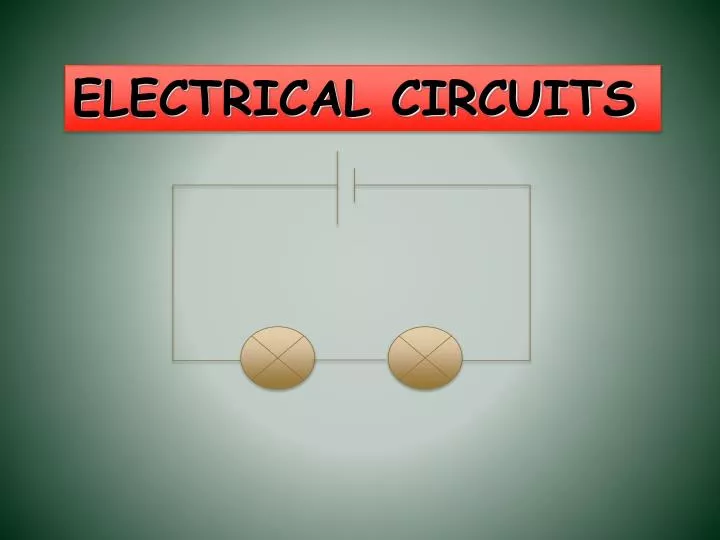
simple circuits Here is a simple electric circuit. It has a cell, a lamp and a switch. wires cell lamp switch To make the circuit, these components are connected together with metal connecting wires.
simple circuits When the switch is closed, the lamp lights up. This is because there is a continuous path of metal for the electric current to flow around. If there were any breaks in the circuit, the current could not flow.
circuit diagram Scientists usually draw electric circuits using symbols; cell lamp switch wires
circuit diagrams In circuit diagrams components are represented by the following symbols; cell battery switch lamp buzzer ammeter voltmeter motor resistor variable resistor
types of circuit There are two types of electrical circuits; SERIES CIRCUITS PARALLEL CIRCUITS
SERIES CIRCUITS The components are connected end-to-end, one after the other. They make a simple loop for the current to flow round. If one bulb ‘blows’ it breaks the whole circuit and all the bulbs go out.
PARALLEL CIRCUITS The components are connected side by side. The current has a choice of routes. If one bulb ‘blows’ there is still be a complete circuit to the other bulb so it stays alight.
measuring current Electric current is measured in amps(A) using an ammeter connected in series in the circuit. A
measuring current This is how we draw an ammeter in a circuit. A A PARALLEL CIRCUIT SERIES CIRCUIT
measuring current SERIES CIRCUIT 2A • current is the same • at all points in the • circuit. 2A 2A PARALLEL CIRCUIT 2A 2A • current is shared • between the • components 1A 1A
copy the following circuits and fill in the missing ammeter readings. ? 3A 3A ? 4A ? 1A ? 4A 4A 1A ? 1A
measuring voltage The ‘electrical push’ which the cell gives to the current is called the voltage. It is measured in volts (V) on a voltmeter V
measuring voltage Different cells produce different voltages. The bigger the voltage supplied by the cell, the bigger the current. Unlike an ammeter a voltmeter is connected across the components Scientist usually use the term Potential Difference (pd) when they talk about voltage.
measuring voltage This is how we draw a voltmeter in a circuit. V V SERIES CIRCUIT PARALLEL CIRCUIT
measuring voltage V V V V
series circuit • voltage is shared between the components 3V 1.5V 1.5V
parallel circuit • voltage is the same in all parts of the circuit. 3V 3V 3V
measuring current & voltage copy the following circuits on the next two slides. complete the missing current and voltage readings. remember the rules for current and voltage in series and parallel circuits.
measuring current & voltage a) 6V 4A A V V A
measuring current & voltage b) 6V 4A A V A V A
answers a) b) 6V 4A 6V 4A 6V 4A 4A 2A 3V 3V 4A 6V 2A
Electric Circuits In electricity, the concept of voltage will be like pressure. Water flows from high pressure to low pressure(this is consistent with our previous analogy that Voltage is like height since DP = rgh for fluids) ; electricity flows from high voltage to low voltage. But what flows in electricity? Charges! How do we measure this flow? By Current: current = I = Dq / Dt UNITS: Amp(ere) = Coulomb / second
The rate at which electrons move along field lines is called drift speed, typically about 10-4 m/s Electric current defined in terms of the flow of positive charge opposite the electrons is called conventional current Current will always be in the same direction as the local electric field
Voltage Sources:batteries and power supplies A battery or power supply supplies voltage. This is analogous to what a pump does in a water system. Question: Does a water pump supply water? If you bought a water pump, and then plugged it in (without any other connections), would water come out of the pump? Question: Does the battery or power supply actually supply the charges that will flow through the circuit?
Charges move from higher to lower potential • For the process to continue, charges that have moved from a higher to lower potential must be raised back to a higher potential again • A battery is able to add charges and raise the charges to higher electric potential Symbol for a battery
Voltage Sources:batteries and power supplies Just like a water pump only pushes water (gives energy to the water by raising the pressure of the water), so the voltage source only pushes the charges (gives energy to the charges by raising the voltage of the charges). Just like a pump needs water coming into it in order to pump water out, so the voltage source needs charges coming into it (into the negative terminal) in order to “pump” them out (of the positive terminal).
Voltage Sources:batteries and power supplies Because of the “pumping” nature of voltage sources, we need to have a complete circuit before we have a current.
Circuit Elements In this first part of the course we will consider two of the common circuit elements: capacitor resistor The capacitor is an element that stores charge for use later (like a water tower). The resistor is an element that “resists” the flow of electricity.
Electrical Resistance & Ohms’ Law The current established is directly proportional to the voltage difference Ohm’s Law: ΔV ∝ I In a plot of ΔV vs I, the slope is called theelectrical resistance
Resistance Current is somewhat like fluid flow. Recall that it took a pressure difference to make the fluid flow due to the viscosity of the fluid and the size (area and length) of the pipe. So to in electricity, it takes a voltage difference to make electric current flow due to the resistance in the circuit.
Resistance By experiment we find that if we increase the voltage, we increase the current: Vis proportional to I. The constant of proportionality we call the resistance, R: V = I*R Ohm’s Law UNITS:R = V/I soOhm = Volt / Amp. The symbol for resistance is
Resistance Just as with fluid flow, the amount of resistance does not depend on the voltage (pressure) or the current (volume flow). The formula V=IR relates voltage to current. If you double the voltage, you will double the current, not change the resistance. The same applied to capacitance: the capacitance did not depend on the charge and voltage - the capacitance related the two. As was the case in fluid flow and capacitance, the amount of resistance depends on the materials and shapes of the wires.
Resistance The resistance depends on material and geometry (shape). For a wire, we have: R = r L / A where r is called the resistivity (in Ohm-m) and measures how hard it is for current to flow through the material,L is the length of the wire, and Ais the cross-sectional area of the wire. The second lab experiment deals with Ohm’s Law and the above equation.
Electrical Power The electrical potential energy of a charge is: U = q*V . Power is the change in energy with respect to time: Power = DU / Dt . Putting these two concepts together we have: Power = D(qV) / Dt = V(Dq) / Dt = I*V.
Electrical Power Besides this basic equation for power: P = I*V remember we also have Ohm’s Law: V = I*R . Thus we can write the following equations for power: P = I2*R = V2/R = I*V . To see which one gives the most insight, we need to understand what is being held constant.
Example When using batteries, the battery keeps the voltage constant. Each D cell battery supplies 1.5 volts, so four D cell batteries in series (one after the other) will supply a constant 6 volts. When used with four D cell batteries, a light bulb is designed to use 5 Watts of power. What is the resistance of the light bulb?
Example We know V = 6 volts, and P = 5 Watts; we’re looking for R. We have two equations: P = I*V and V = I*R which together have 4 quantities: P, I, V & R.. We know two of these (P & V), so we should be able to solve for the other two.
Example Using the power equation we can solve for I: P = I*V, so 5 Watts = I * (6 volts), or I = 5 Watts / 6 volts = 0.833 amps. Now we can use Ohm’s Law to solve for R: V = I*R, so R = V/I = 6 volts / 0.833 amps = 7.2 W .
Example extended If we wanted a higher power light bulb, should we have a bigger resistance or a smaller resistance for the light bulb? We have two relations for power that involve resistance: P=I*V; V=I*R; eliminating V gives: P = I2*R and P=I*V; I=V/R; eliminating I gives:P = V2 / R . In the first case, Power goes up as R goes up; in the second case, Power goes down as R goes up. Which one do we use to answer the above question?
Example extended Answer: In this case, the voltage is being held constant due to the nature of the batteries. This means that the current will change as we change the resistance. Thus, the P = V2 / R would be the most straight-forward equation to use. This means that as R goes down, P goes up. (If we had used the P = I2*R formula, as R goes up, I would decrease – so it would not be clear what happened to power.) The answer: for more power, lower the resistance. This will allow more current to flow at the same voltage, and hence allow more power!
Kirchhoff’s Laws • Junction Law: at a junction in a circuit, the sum of the current entering the junction will equal the sum of the current leaving. Σ I = Σ I in out • Loop Law: the sum of the potential drops around any closed loop must add to Σ V = 0 loop
Connecting Resistors There are two basic ways of connecting two resistors: series and parallel. In series, we connect resistors together like railroad cars; this is just like we have for capacitors: + - + - high V low V R1 R2
Formula for Series: To see how resistors combine to give an effective resistance when in series, we can look either at V = I*R, or at R = rL/A . R1 I V1 + R2 Vbat V2 -
Formula for Series Using V = I*R, we see that in series the current must move through both resistors. (Think of water flowing down two water falls in series.) Thus Itotal = I1 = I2. Also, the voltage drop across the two resistors add to give the total voltage drop: (The total height that the water fell is the addition of the two heights of the falls.) Vtotal = (V1 + V2). Thus, Reff = Vtotal / Itotal = (V1 + V2)/Itotal = V1/I1 + V2/I2 = R1 + R2.
Formula for Series Using R = rL/A , we see that we have to go over both lengths, so the lengths should add. The distances are in the numerator, and so the values should add. This is just like in R = V/I(from V = IR) where the V’s add and are in the numerator! Note: this is the opposite of capacitors when connected in series! Recall that C = Q/V, where V is in the denominator!
Formula for Parallel Resistors The result for the effective resistance for a parallel connection is different, but we can start from the same two places: (Think of water in a river that splits with some water flowing over one fall and the rest falling over the other but all the water ending up joining back together again.) V=I*R, or R = rL/A . Itotal + Vbat I1 R1 R2 I2 -
Formula for Parallel Resistors V=I*R, or R = rL/A For parallel, both resistors are across the same voltage, so Vtotal = V1 = V2. The current can go through either resistor, so: Itotal = (I1 + I2 ). Since the I’s are in the denominator, we have: R = Vtotal/Itotal = Vtotal/(I1+I2); or 1/Reff = (I1+I2)/Vtotal = I1/V1 + I2/V2 = 1/R1 + 1/R2.