Download
1 / 47
470 likes | 589 Views
Project: IEEE P802.15 Working Group for Wireless Personal Area Networks (WPANs) Submission Title: Merged IPC and TI Adaptive Frequency Hopping Proposal Date Submitted: May 14, 2001 Source: (1) KC Chen, HK Chen, CC Chao (2) Anuj Batra, Kofi Anim-Appiah, and Jin-Meng Ho

E N D
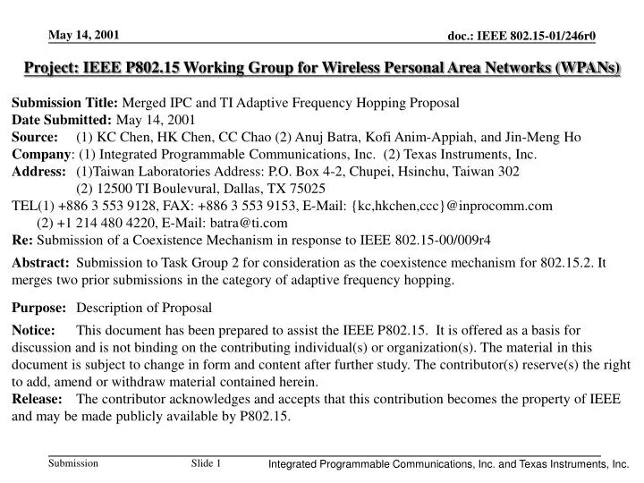
Project: IEEE P802.15 Working Group for Wireless Personal Area Networks (WPANs) Submission Title:Merged IPC and TI Adaptive Frequency Hopping Proposal Date Submitted: May 14, 2001 Source: (1) KC Chen, HK Chen, CC Chao (2) Anuj Batra, Kofi Anim-Appiah, and Jin-Meng Ho Company: (1) Integrated Programmable Communications, Inc. (2) Texas Instruments, Inc. Address: (1)Taiwan Laboratories Address: P.O. Box 4-2, Chupei, Hsinchu, Taiwan 302 (2) 12500 TI Boulevural, Dallas, TX 75025 TEL(1) +886 3 553 9128, FAX: +886 3 553 9153, E-Mail: {kc,hkchen,ccc}@inprocomm.com (2) +1 214 480 4220, E-Mail: batra@ti.com Re: Submission of a Coexistence Mechanism in response to IEEE 802.15-00/009r4 Abstract: Submission to Task Group 2 for consideration as the coexistence mechanism for 802.15.2. It merges two prior submissions in the category of adaptive frequency hopping. Purpose: Description of Proposal Notice: This document has been prepared to assist the IEEE P802.15. It is offered as a basis for discussion and is not binding on the contributing individual(s) or organization(s). The material in this document is subject to change in form and content after further study. The contributor(s) reserve(s) the right to add, amend or withdraw material contained herein. Release: The contributor acknowledges and accepts that this contribution becomes the property of IEEE and may be made publicly available by P802.15. Integrated Programmable Communications, Inc. and Texas Instruments, Inc.
Merged IPC and TIAdaptive Frequency Hopping Proposal KC Chen, HK Chen, CC Chao Integrated Programmable Communications, Inc. Anuj Batra, Kofi Anim-Appiah, and Jin-Meng Ho Texas Instruments Integrated Programmable Communications, Inc. and Texas Instruments, Inc.
Outline • Present the unified framework for a merged adaptive frequency hopping proposal. • Also, we will present an enhancement (ESHA) for the SCO link from Selective Hopping for Hit Avoidance (SHA). • Finally, we will show the relationship of this merged proposal to other proposals presented in 802.15.2. Integrated Programmable Communications, Inc. and Texas Instruments, Inc.
Unified Framework for Merged Proposal Integrated Programmable Communications, Inc. and Texas Instruments, Inc.
Bluetooth Degradation • In an interference-limited environment, the throughput for a Bluetooth device is often degraded. • The throughput, however, can be improved by avoiding bad channels. • One way to avoid the bad channels is to rearrange the hopping sequence (introduce some structure). • The “Two Layer Structure” can be used to rearrange (modify) the original Bluetooth hopping sequence. Integrated Programmable Communications, Inc. and Texas Instruments, Inc.
Two Layer Structure for HS RF input signal Frequency synthesizer Partition mapping partition sequence Original hopping sequence generator Hop clock Integrated Programmable Communications, Inc. and Texas Instruments, Inc.
Partitions • “Two Layer Structure” is based on partitions of the Bluetooth channels. • The partition sequences specify “when” to use “which” partition. They are designed for optimal coexistence performance. • The partition mapping • It primary function is to select one channel in the given partition • We maintain the pseudo-random property of the original Bluetooth hopping sequence. • Example of a frequency partition is given on the next slide. Integrated Programmable Communications, Inc. and Texas Instruments, Inc.
Partition number Corresponding Bluetooth channel number* Total channels in this partition Corresponding 802.11b Channel number 1 0-22,75-77 26 1 2 23-47,74 26 6 3 48-72,73 26 11 Example of Frequency Partition *Channel 78 is not involved in any partitions to equalize the size of each partition. Integrated Programmable Communications, Inc. and Texas Instruments, Inc.
Definition of Partitions • For an SCO link, use the three partitions described on previous slide. • For an ACL link, use two partitions: • Partition 1 is composed of the good channels (length = NG). • Partition 2 is composed of the bad channels (length = NB). • Let Nmin = min. frequencies defined by FCC and min. needed for frequency diversity. Nmin NG + NB 79 • Note that it possible some of the channels are unused, i.e., there are not in either partition. Integrated Programmable Communications, Inc. and Texas Instruments, Inc.
Partition Sequence for an SCO Link • For an SCO link, select a partition sequence from the table given on next slide. • The selection is performed at the master only. • A baseline selection algorithm is provided. • A least part of the selection algorithm has to be standardized • To guarantee the coexistence performance • If one manufacturer implements this algorithm incorrectly, then all of Bluetooth manufacturers will suffer, esp. in the press. • To keep interoperability • The partition sequences and necessary parameters are then sent to each slave in the piconet. Integrated Programmable Communications, Inc. and Texas Instruments, Inc.
Baseline Partition Sequence Selection Algorithm for an SCO link(1) • Calculate a hit ratio for each partition as the ratio of the number of interference events to the number of total events • For partitions with interference hit ratios below threshold, corresponding hit ratios are set to be zero. • From the time slots reserved by the traffic requirements, calculate the partition usage vector for each of the partition sequences. • Select the partition sequence with minimal H(p) Integrated Programmable Communications, Inc. and Texas Instruments, Inc.
Baseline Partition Sequence Selection Algorithm for an SCO Link(2) • Definition of H(p) • H(p) is defined for each sequence p with given traffic requirement, where Np is the number of partitions, R(k) is the measured hit ratio of the k-th partition, uk(p) is the k-th element of the partition usage vector of the partition sequence p. • A sequence that utilizes better partitions (lower hit ratios) more frequently has lower H(p). Integrated Programmable Communications, Inc. and Texas Instruments, Inc.
Baseline Partition Sequence Selection Algorithm for an SCO Link(3) • Definition of partition usage vector • The partition usage vector U(p) is calculated for a partition sequence p given the time slots reserved by traffic requirement. • The k-th element of U(p), uk(p), is proportional to the relative frequency of partition k in the reserved time slots. Integrated Programmable Communications, Inc. and Texas Instruments, Inc.
Baseline Partition Sequence Selection Algorithm for an SCO Link(4) • Example of partition usage vector • Partition sequence= Repeating {1 2 3 1 3 2}, time unit= 2 slots Integrated Programmable Communications, Inc. and Texas Instruments, Inc.
A Set of Partition Sequences Integrated Programmable Communications, Inc. and Texas Instruments, Inc.
Partition Sequence for an ACL Link • Consider the following hopping sequence with fixed block lengths: • For an ACL link, the sequence is completely described by parameters RG and RB. • The equations for selecting RG and RBare give innext 2 slides. • For this link, the partition sequence is binary (either 1 or 2). • This sequence and the necessary parameters are then sent to each slave within the piconet. Integrated Programmable Communications, Inc. and Texas Instruments, Inc.
Parameters for ACL Link (1) • Note: • During blocks of good channels: 100% of packets are received. • During blocks of bad channels: 0% packets are received. • Define “Dead Time” = DT = 625 ms · RB. • To comply with FCC regulations, need addition restriction: • Process for selecting: • “Dead Time” requirement for application dictates value of RB. • Given g, RG must satisfy FCC constraint. • If RG = 0, then must use a larger value of RB. Integrated Programmable Communications, Inc. and Texas Instruments, Inc.
Parameters for ACL Link (2) • Assume a fully-loaded link, where the master-to-slave packet is DM/H-M and where the slave-to-master packet is DM/H-S. • The optimal values for the block lengths are given by: • The aggregate throughput is then given by: Integrated Programmable Communications, Inc. and Texas Instruments, Inc.
Channel in the original hopping sequence Desired partition specified by the partition sequence action Good Good Keep the same Good\Unused Bad Mapping Bad \Unused Good Mapping Bad Bad Keep the same Channel Mapping • Want to design a new hopping sequence that shares many of the same channels as the original hopping sequence. • This new sequence will have many advantages: • It is backwards compatible, i.e., can support both the old and new sequences in the same piconet. • It supports broadcast packets. • Helps to maintain channel hop clock synchronization. Integrated Programmable Communications, Inc. and Texas Instruments, Inc.
Pseudo-random mapping Maintain the pseudo-random property of the original hopping sequence Mapping table of this partition Selected channel number of original hopping sequence (0~78) Mod Nj Nj shifter signal Size of partition Bad Good Current partition = j (from partition sequence) Integrated Programmable Communications, Inc. and Texas Instruments, Inc.
Shifter Signal • If the input is uniformly distributed in the range [0, N – 1], then the output of MOD(Nj) will not be uniformly distributed, unless N is multiple of Nj. • To force a uniform output distribution, we add a “shifter signal” to the input. • A simple example of a shifter signal is given by: • Two counters, one for each partition. • Each counter has the range [0, Nj – 1]. • The counter of selected partition counts up by one each time. Integrated Programmable Communications, Inc. and Texas Instruments, Inc.
Channel Quality Assessment (1) • Leave actual method for channel quality assessment undefined. • Each manufacturer will have its own proprietary implementation • Examples • From the combination of RSSI and error detection (HEC, CRC, FEC) • Listen to the channel during channel idle time • Special hardware to detect some specific interference, such as 802.11b CCA • Divide the band into N sub-bands for detection • Small N for fast assessment, large N for better frequency resolution • N=3 for 802.11b at channel 1, 6, 11 • N=79 for access each channel independently • 3<N<79 as a compromised solution Integrated Programmable Communications, Inc. and Texas Instruments, Inc.
Channel Quality Assessment (2) • Regardless of the real implementation, the result can be mapped to the same format: • A list of 79 items, one for each channel, indicating the corresponding channel is good/bad/unused, requiring 2*79=158 bits. • Unused channels allow to use less than 79 channels. • The recommended practice: • Should have standardized format and procedure to exchange the information of channel quality assessment • May include suggested values for assessment time • The requirement for assessment time is application specific. • SCO link should demand shorter assessment time. Integrated Programmable Communications, Inc. and Texas Instruments, Inc.
Enhancements to the SCO link Integrated Programmable Communications, Inc. and Texas Instruments, Inc.
Enhanced SHA (ESHA) for SCO Link • Enhancement: • Takes full advantage of the possibility that good channels may reside in the bad partition. • Most effective for narrowband interference sources and possibly narrowband 802.11b signals. Integrated Programmable Communications, Inc. and Texas Instruments, Inc.
Description of Enhancements • What stays the same: • “Two layer structure” to modify hopping sequence. • Pseudo-random mapping device. • The idea of allocating good channels in the good partitions for the SCO link remains the same. • What is new: • The partitioning is now dynamic, as was done for the ACL link. • An algorithm to generate the new partition sequence. • This algorithm replaces the “select one from the table” method. Integrated Programmable Communications, Inc. and Texas Instruments, Inc.
System Architecture Interference indicator from integrated / collocated devices RF input signal Channel interference measurement Channel partitioning Modified blocks are red Packet target Frequency synthesizer Partition sequence change procedure Original/Mapped sequence selection Multiplexer Partition sequence generation Partition mapping re-mapping Hopping sequence generation Traffic requirement Channel usage requirement Hop clock Integrated Programmable Communications, Inc. and Texas Instruments, Inc.
Partitioning for Enhanced SHA • Exactly the same as that for the ACL link. • The contents of the partitions are now dynamic: • Partition 1 is composed of the good channels (length = NG). • Partition 2 is composed of the bad channels (length = NB). • Let Nmin = min. frequencies defined by FCC and min. needed for frequency diversity. Nmin NG + NB 79 • Note that it possible some of the channels are unused, i.e., there are not in either partition. Integrated Programmable Communications, Inc. and Texas Instruments, Inc.
Partition Sequence for ESHA (1) • Focus on HV2 and HV3 links. • Let MAU be the minimal allocation unit. • MAU = 2 hops master and slave slots are in the same partition. • Let the Frame be matched to the period of the HV link. • For HV2: one Frame = 2 MAUs = 4 hops. • For HV3: one Frame = 3 MAUs = 6 hops. Integrated Programmable Communications, Inc. and Texas Instruments, Inc.
Super-frame Super-frame Super-frame frame frame 0 2 Ls -1 1 1 0 2 Lf -1 MAU Partition Sequence for ESHA (2) • Structure of partition sequence: • Let the Super-frame be the period of partition sequence. • Each super-frame is composed of Ls frames, and each frame is composed of Lf MAU. Integrated Programmable Communications, Inc. and Texas Instruments, Inc.
Partition Sequence for ESHA (3) • Why use a super-frame? • One average, each frame should have MG good MAUs: • However, MGis not an integer in general. • Solution: use a super-frame, which is composed of Ls frames: • Now one super-frame will have MGgood MAUs: • Select Ls in such a way as to MGan integer. • Can force these MGMAUs to be uniformly distributed in each frame. Integrated Programmable Communications, Inc. and Texas Instruments, Inc.
Partition Sequence for ESHA (4) • Partition sequence generation procedure: • Calculate MG, the number of good MAUs in a super-frame. • Distribute these MG MAUs to the Ls frames. • The i-th frame will have m(i,G) good MAUs. • Arrange the order of MAUs within each frame according to the traffic requirement. Integrated Programmable Communications, Inc. and Texas Instruments, Inc.
Partition Sequence for ESHA (5) • Number of MAUs of the good/bad partition: MG/MB • Number of MAUs of the good/bad partition in the i-th frame: m(i,G) / m(i,B) • The first term is the maximal integer number of good MAUs that each frame can have. • The second term d(i) is in the set {0,1}, indicating the frames having one more good MAUs. Integrated Programmable Communications, Inc. and Texas Instruments, Inc.
Partition Sequence for ESHA (6) • Equations for d(i) • The residue good MAUs need to distribute • To minimize the max spacing ‘c’ between these residue good MAUs when spreading them into Ls frames Integrated Programmable Communications, Inc. and Texas Instruments, Inc.
Partition Sequence for ESHA (7) • The order of MAUs within each frame according to the traffic requirement • Traffic priority sequence: • A SCO slot will have a priority of 0 and it is the higher priority traffic • a non-SCO slot will have a priority of 1 and it is the lower priority traffic. • Rules: • A slot with priority 0 has higher preference for the good MAU • If there are two slots with the same priority number, the first slot in time has higher preference for the good MAU Integrated Programmable Communications, Inc. and Texas Instruments, Inc.
Symbol Value Description 11 Number of frames per super-frame 3 Number of MAUs per frame 2 Number of hops per MAU 11 Number of used channels 5 Number of channels in partition 1(good partition) 6 Number of channels in partition 2 (bad partition) ESHA Partition Sequence Example (1) Integrated Programmable Communications, Inc. and Texas Instruments, Inc.
P2 P2 P2 P2 P2 P2 P2 P2 P2 P2 P2 P1 P2 P2 P1 P2 P2 P1 P2 P2 P1 P2 P1 P1 P1 P1 P1 P1 P1 P1 P1 P1 P1 Frame 0 1 2 3 4 5 6 7 8 9 10 ESHA Partition Sequence Example (2) • Illustration of distributing the MG MAUs good bad Integrated Programmable Communications, Inc. and Texas Instruments, Inc.
Hop clock%6 i=0 0 1 2 1 3 2 4 5 3 6 4 7 8 5 9 10 m(i,G) Reserved hop 2 1 1 2 Reserved 1 1 Reserved 2 1 1 2 1 m(i,B) 1 2 2 1 2 2 1 2 2 1 2 MAU slot 0 1 2 Traffic priority sequence 1 0 1 ESHA Partition Sequence Example (3) The number of MAUs in each frame: Traffic requirement (one HV3, Dsco=2,3): Integrated Programmable Communications, Inc. and Texas Instruments, Inc.
ESHA Partition Sequence Example (4) • The resulting partition sequence: Integrated Programmable Communications, Inc. and Texas Instruments, Inc.
Relationship to Other Proposals Integrated Programmable Communications, Inc. and Texas Instruments, Inc.
Relationship to other proposals (1) • If the number of good channels in the band is greater than Nmin, then: • We can choose NB= 0. • Recall the restriction: Nmin NG + NB. • The adaptive frequency hopping algorithm therefore reduces to using only the good channels. • Note that in this case, the partition sequence becomes a constant signal. • For this case, the merged proposal is very similar to the one proposed by Bandspeed. Integrated Programmable Communications, Inc. and Texas Instruments, Inc.
Relationship to other proposals (2) • Relationship to Bandspeed’s proposal • The merged proposal degenerates to use a single good parition when there are enough good channels • The same nice property: design a new hopping sequence that shares many of the same channels as the original hopping sequence. • The only difference left is the mapping device, periodic or pseudo-random. Integrated Programmable Communications, Inc. and Texas Instruments, Inc.
Relationship to other proposals (3) • Relationship to Eliezer’s proposal • The size of the good paritition is fixed as 23 channels • Use the good partition only • The mapping device is periodic. Integrated Programmable Communications, Inc. and Texas Instruments, Inc.
Conclusions • New algorithm effectively support both SCO and ACL links. • Guarantees services under certain traffic conditions. • Performs well even in the presence of interference. • The algorithm is simple and backwards compatible: • Can be implemented as a stand-alone module. • Sequence is generated at master to prevent complicated two-way exchange of information (avoid delay). • Works with existing FCC rules. Also flexible to work with new FCC rules. Integrated Programmable Communications, Inc. and Texas Instruments, Inc.
References • K. C. Chen, H. K. Chen, C. C. Chao, Selective Hopping for Hit Avoidance [01/057r2] • A. Batra, K. Anim-Appiah, J.-M. Ho, An Intelligent Frequency Hopping Scheme for Improved Bluetooth Throughput in an Interference-Limited Environment [01/082r1] • H. B. Gan etal., Adaptive Frequency Hopping [00/367r1] Integrated Programmable Communications, Inc. and Texas Instruments, Inc.
Merged Proposal Response to Evaluation Criteria (I) • Collaborative or Non-collaborative: • Its default setup is non-collaborative but collaborative is also defined. • Improved WLAN and WPAN Performance: • WPAN throughput increases. • WLAN BER/throughput improves. • Impacts on Standards: • Minimum changes (ACL/SCO) in WPAN. • Regulatory Impact • None and future changes are allowed. • Complexity: • One extra implementation module in link-layer. Integrated Programmable Communications, Inc. and Texas Instruments, Inc.
Merged Proposal Response to Evaluation Criteria (II) • Interoperability with systems that do not include co-existence mechanism: • Yes. • Impact on Interface to Higher Layers: • None. • Applicability to Classes of Operation: • Yes. • Voice and Data Support in Bluetooth: • Yes. • Impact on Power Management: • Increases life of battery because devices will not transmit on bad channels. Integrated Programmable Communications, Inc. and Texas Instruments, Inc.