Download
1 / 21
210 likes | 315 Views
1. 10. 01. 1. 1. 1. 1. Key Observation. Adjacencies in the K-Map. 111. 011. B. BC. 00. 01. 11. 10. A. 010. 110. 0. 000. 010. 100. 001. B. 001. 101. 1. 101. C. 000. C. 100. A. Any two adjacant cells in the K-map differ in exactly one variable.

E N D
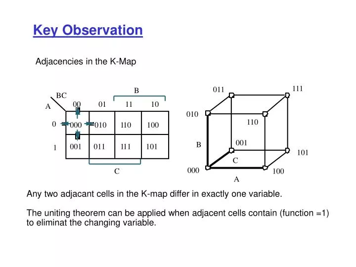
1 10 01 1 1 1 1 Key Observation Adjacencies in the K-Map 111 011 B BC 00 01 11 10 A 010 110 0 000 010 100 001 B 001 101 1 101 C 000 C 100 A Any two adjacant cells in the K-map differ in exactly one variable. The uniting theorem can be applied when adjacent cells contain (function =1) to eliminat the changing variable.
Design Examples Two Bit Comparator Truth Table Block Diagram Design Steps: 1- Simplify to reduce cost (three 4-variable K-maps, one for each output) 2- Implement using a suitable design style (e.g. 2-level AND-OR, NAND-NAND, or multilevel techniques)
Design Examples Two Bit Comparator (continued) F1 = A' B' C' D' + A' B C' D + A B C D + A B' C D' F2 = A' B' D + A' C F3 = B C' D' + A C' + A B D' f1 = AC(BD+bd) + ac(bd+BD) = (AC+ac) (bd+BD) = (a c) (b d)
Design Examples Two-Bit Adder Truth Table Block Diagram
A A A AB AB AB 00 01 11 10 00 01 11 10 00 01 11 10 CD CD CD 00 0 0 0 0 00 0 0 1 1 00 0 1 1 0 01 0 0 1 0 01 0 1 0 1 01 1 0 0 1 D D D 11 0 1 1 1 11 1 0 1 0 11 1 0 0 1 C C C 10 0 0 1 1 10 1 1 0 0 10 0 1 1 0 B B B K-map for X K-map for Y K-map for Z Design Example Two-Bit Adder (Continued) X = A C + B C D + A B D Z = B D' + B' D = B xor D Y = A' B' C + A B' C' + A' B C' D + A' B C D' + A B C' D' + A B C D
B B ABC 000 001 011 010 100 101 111 110 DE 00 1 1 01 E 11 1 1 1 1 D 1 1 1 1 10 C C B B ABC 000 001 011 010 100 101 111 110 DE 1 1 1 1 00 01 1 1 1 1 1 1 11 D 1 1 1 1 10 C C 5-Variable K-Maps Constructed from two 4-variable K-Maps. A = 0 A = 1 f = bCDE + Bd E g = ABe + Bce + bE
5-Variable K-Maps Another View ƒ(A,B,C,D,E) = Sm(2,5,7,8,10,13,15,17,19,21,23,24,29 31) ƒ(A,B,C,D,E) = C E + A B' E + B C' D' E' + A' C' D E'
6-Variable K-Maps ƒ(A,B,C,D,E,F) = Sm(2,8,10,18,24, 26,34,37,42,45,50, 53,58,61)
6-Variable K-Maps ƒ(A,B,C,D,E,F) = Sm(2,8,10,18,24, 26,34,37,42,45,50, 53,58,61) = D' E F' + A D E' F + A' C D' F'
CD Definitions • Implicant: Single 1 entry or any group of 1’s that can be combined together in a K-map to form a product term. • (Dual): Single 0 entry or any group of 0’s that can be combined together in a K-map to form a sum term. • Prime Implicant: an implicant that cannot be combined with another • implicant to eliminate a term • Essential Prime Implicant: a prime implicant that contains a 1 entry • not covered by any other implicant. Example C 6 Prime Implicants: 00 01 11 10 AB A' B C’ , C D, A‘ D , B C' D’ , A C , AB D' 00 0 1 1 0 01 1 1 1 0 B essential 11 1 0 1 1 A Minimum cover = A’ D + A C + B C ‘ D ’ 10 0 0 1 1 D
CD Definitions • Implicant: Single 1 entry or any group of 1’s that can be combined together in a K-map to form a product term. • (Dual): Single 0 entry or any group of 0’s that can be combined together in a K-map to form a sum term. • Prime Implicant: an implicant that cannot be combined with another • implicant to eliminate a term • Essential Prime Implicant: a prime implicant that contains a 1 entry • not covered by any other implicant. Example C 00 01 11 10 AB 00 0 1 1 0 01 1 1 1 0 B 11 1 0 1 1 A 10 0 0 1 1 D
Illustrating the Definitions Prime Implicants: B D, C D, A C, B' C essential Essential primes form the minimum cover 5 Prime Implicants: B D, A B C', A C D, A' B C, A' C' D essential Essential implicants form minimum cover
CD Illustrating the Definitions C Prime Implicants: 00 01 11 10 AB A D’, AB, A C, BD 00 0 0 0 0 essential 01 0 1 1 0 B 11 1 1 1 1 Essential primes form the minimum cover A 10 1 0 1 1 D Try the other axis 5 Prime Implicants: B D, A B C', A C D, A' B C, A' C' D essential Essential implicants form minimum cover
Quine-McCluskey (Tabular) Method systematically finds all prime implicants Example: Simplify ƒ(A,B,C,D) = Sm(4,5,6,8,9,10,13) + Sd(0,7,15) Implication Table Column I 0000 0100 1000 0101 0110 1001 1010 0111 1101 1111 Step 1: List minterms and don’t cares using their binary representation, and group according to number of 1’s Principle: Combine terms in adjacent groups which differ in a single variable, and eliminate the changing variable. Remarks: Only terms in adjacent groups have to be compared with one another. Terms in non-adjacent groups differ in more than one variable. Thus can not be combined
Q & M Method ƒ(A,B,C,D) = Sm(4,5,6,8,9,10,13) + Sd(0,7,15) • Step 2: • Compare elements of a group with • k 1's against those with k+1 1's. • If they differ by one bit, eliminate • changing variable and place reduced • term in next column. • E.g., 0000 vs. 0100 yields 0-00 • 0000 vs. 1000 yields -000 Implication Table Column I Column II 0000 ¦ 0-00 -000 0100 ¦ 1000 ¦ 010- 01-0 0101 ¦ 100- 0110 ¦ 10-0 1001 ¦ 1010 ¦ 01-1 -101 0111 ¦ 011- 1101 ¦ 1-01 1111 ¦ -111 11-1 When a term is used in a combination, mark that term with a check. If cannot be combined, mark term with a star. These are the prime implicants.
Q & M Method • Step 2 Continues: • Compare elements of a group in • Col. II with • k 1's against those with k+1 1's. • If they differ by one bit, eliminate • changing variable and place reduced • term in next column. • E.g., 010- vs. 011- yields 01- - • -101 vs. -111 yields -1-1 Implication Table Column I Column II Column III 0000 ¦ 0-00 * 01-- * -000 * 0100 ¦ -1-1 * 1000 ¦ 010- ¦ 01-0 ¦ 0101 ¦ 100- * 0110 ¦ 10-0 * 1001 ¦ 1010 ¦ 01-1 ¦ -101 ¦ 0111 ¦ 011- ¦ 1101 ¦ 1-01 * 1111 ¦ -111 ¦ 11-1 ¦
Q & M - Prime Implicant Chart x x x x x x 5,7,13,15 (-1-1) 4,5,6,7(01--) 9,13(1-01) 8,10(10-0) 8,9(10-0) 0,8(-000) 0,4(0-00) 5,7,13,15 (-1-1) 4,5,6,7(01--) 9,13(1-01) 8,10(10-0) 8,9(10-0) 0,8(-000) 0,4(0-00) x x x x x x x x x x x x x x x x x x x x 4 5 6 8 9 10 13 4 5 6 8 9 10 13 rows = prime implicants columns = minterms place an "X" if minterm is covered by the prime implicant If column has a single X, than the implicant associated with that row is essential. It must appear in minimum cover
Description T ruth T able If X = 0 then X ' = 1 X X T rue If X = 1 then X ' = 0 0 1 1 0 Description T ruth T able Z = 1 if X or Y X Y Z (or both) are 1 0 0 0 X + Y 0 1 1 T rue 1 0 1 1 1 1 X Y Gate Logic • Review Switches NOT X False X Description Truth Table Switches Z = 1 if X and Y X Y Z false are both 1 0 0 0 AND X • Y 0 1 0 1 0 0 true 1 1 1 X Y Switches False OR
c s e d w a d e’ s 1 a c’ w Example : Logic circuit & its Switch realization s = a (d+w)(c’+ e’) Gate realization Switch realization
Description T ruth T able Z = 1 if X is 0 T rue X Y Z or Y is 0 0 0 1 X • Y 0 1 1 1 0 1 1 1 0 X Y Logic Functions: NAND Switches NAND False Description Truth Table Switches Z = 1 if X and Y X Y Z false AND are both 1 0 0 0 X • Y 0 1 0 1 0 0 true 1 1 1 X Y Note that switch circuit of the NAND gate is the complement of the switch circuit for the AND gate.
Description T ruth T able Z = 1 if both X X Y Z T rue and Y are 0 0 0 1 0 1 0 X + Y 1 0 0 1 1 0 X Y Description T ruth T able Z = 1 if X or Y X Y Z (or both) are 1 0 0 0 X + Y 0 1 1 T rue 1 0 1 1 1 1 X Y Logic Functions: NAND, NOR, XOR, XNOR Switches NOR False Switches False OR Note that switch circuit of the NOR gate is the complement of the switch circuit for the OR gate.