Download
1 / 21
220 likes | 540 Views
Multilevel Logic Minimization -- Introduction. Outline. Multi-level minimization: technology independent local optimization. What to optimize: multi-level logic modeled as Boolean networks Optimization targets: # of literals What’s new: Don’t cares Don’t cares in multi-level logic

E N D
Outline • Multi-level minimization: technology independent local optimization. • What to optimize: multi-level logic modeled as Boolean networks • Optimization targets: # of literals • What’s new: Don’t cares • Don’t cares in multi-level logic • Internal vs. external • Satisfiablity vs. observablity • Using don’t cares for multi-level minimization ENEE 644
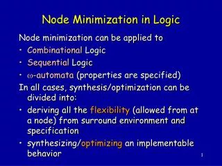
x1 x2 x3 x4 x5 x6 y1 y2 y3 y4 y5 Boolean Network: Example • A Boolean network is an acyclic graph. • Each node of the graph is a gate (may not be basic). • Each edge implies a connection between two gates. • Example: • Description of the network: • y1 = x’2 + x’3(NAND) • y2 = x’4 + x’5(NAND) • y3 = x’4y’1(NOR) • y4 = x1 + y’3 • y5 = x6y2 + x’6y’3 ENEE 644
Boolean Network: Definition A Boolean network is an interconnection of Boolean functions defined by a five-tuple: • f = (f1,…,fn) n completely specified logic functions (gates); • y = (y1,…,yn) n logic variables that are in one-to-one correspondence with f (signals of the network); • I = (I1,…Ip) p primary inputs; • O = (O1,…,Oq) q primary outputs; • dX = (d1X,…,dqX) completely specified logic functions for the don’t care minterms on the outputs. It is convenient to consider both I and O as functions. We denote x = (x1,…,xp) = (y1,…,yp) and z = (z1,…,zq) = (yn-q+1,…,yn-1,yn) as the I-component (primary inputs) and O-component (primary outputs) of vector y. ENEE 644
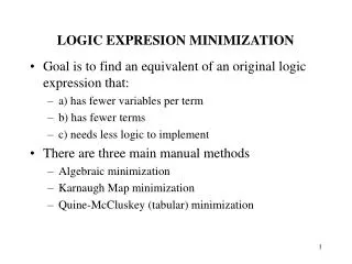
1 4 a 6 9 S 5 7 2 8 10 b C 3 c Example: Full Adder • f: f1 buffer,…, f4 XOR, f5 AND,…, f8 OR,…, f10 buffer • y: 1, 2, 3, 4, 5, 6, 7, 8, 9, 10 • I: 1,2,3 • O: 9, 10 • dX: ENEE 644
Boolean Network: As a Digraph G=(V,E): DAG • V: each function is a node (node i fi yi). • E: there is a directed edge from node i to node j if yi supp(fj), denoted by (i,j) E. If (i,j) E, node i is a predecessor (input, fanin) of node j, and node j is a successor (output, fanout) of node i; If there is a path from node i to node j, node i is a transitive predecessor (transitive fanin) of node j, and node j is a transitive successor (transitive fanout) of node i. Pi = {jV | (j,i) E} Si = {jV | (i,j) E} Pi* = {jV | node j is a transitive fanin of node i} Si* = {jV | node j is a transitive fanout of node i} ENEE 644
1 4 a 6 9 S 5 7 2 8 10 b C 3 c Example: Full Adder • P4={1,2}, P8={5,7}, P9={6}, P2= • S4={6,7}, S8={10}, S9=, S2= {4,5} • P4*={1,2}, P8*={1-5,7}, P9*={1-4,6}, P2*= • S4*={6-10}, S8*={10}, S9*=, S2*= {4-10} ENEE 644
Boolean Network: Net and Connection • Each signal in the Boolean network represents the voltage on a segment of interconnect/wire in the circuit that implements the Boolean network. This wire segment is referred as a net. • The logic value on a net is determined by the source terminal, a logical signal corresponding to a specific node yi in the Boolean network. • Inputs to the nodes in the fanout Si are sink terminals. • Source and sink terminals are called pins of the net. • Each edge (i,j) E is also called a connection, denoted by cij with a logic variable yij. • Pij = i, Sij = j, Pij* = Pi*{i}, Sij* = Sj*{j} ENEE 644
Example: Full Adder • XOR gate 6 produces logical signal y6; its output is the source terminal of corresponding net; this net has a single sink terminal on the input of buffer 9. • For the connection C6,9 from 6 to 9, we have: P6,9=6, S6,9=9, P6,9*=P6* {6}={1-4,6}, S6,9* = S9*{9}=9 1 4 a 6 9 S 5 7 2 8 10 b C 3 c ENEE 644
Boolean Network: Global Functions • Functions fi(y) are local functions in that they are specified by the neighbors of node i in the Boolean network. • The global functionsfi*(x)=(I,fi(y))are defined on a subset of primary inputs, where the composition operator is defined recursively as: yi if iA (A,fi(y)) = fi if PiA fi((A,fPi(1)), (A,fPi(2)),…, (A,fPi(|Pi|))) otherwise ENEE 644
1 4 a 6 9 S 5 7 2 8 10 b C 3 c Example: Full Adder • f3* = (I,f3) = y3 • f5* = (I,f5) = f5 = y1y2 • f9* = (I,f9) = (I,f6) = XOR((I,f4), (I,f3)) =XOR(XOR((I,f1),(I,f2)),y3) =XOR(XOR(y1,y2),y3) ENEE 644
Don’t Cares: Satisfiability Don’t Care • Satisfiability don’t care (SDC) occurs when certain input combination to a circuit can never occur. • How it happens? • We may represent a node using both primary inputs and intermediate variables. (Bn+m) • The intermediate variables depend on primary inputs. • So, not all the minterms of Bn+m can occur. • Example: • y = a+b, then {y=0, a=1, b=-} will never occur (SDC). ENEE 644
Computing SDCs ENEE 644
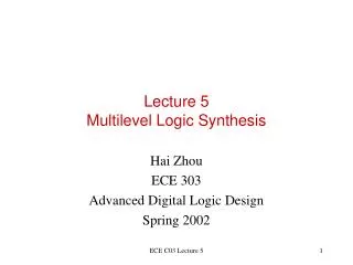
1 8 10 a F=a+bcd+e 2 b 3 6 c 11 9 4 d G=a+cd g 5 7 e Example: Minimization Using SDCs • Introduce intermediate variable g at node 9. • Cannot do resubstitution since F/g = 0. • What is the difference between bcd and bg (xor of the two)? • bcdg’, bc’g, bd’g. ENEE 644
1 8 10 a F=a+bcd+e 2 b 3 6 c 11 9 4 d G=a+cd g 5 7 e Example: Minimization Using SDCs • SDC9=g(a+cd)=g’a+g’cd+ga’c’+ga’d’ • bcdg’ is covered by g’cd • bc’g=abc’g+a’bc’g is covered by a + ga’c’ • bd’g=abd’g+a’bd’g is covered by a + ga’d’ • F = a + bg + e ? bcdg’,bc’g, bd’g ? ENEE 644
Don’t Cares: Observability Don’t Care • Observability don’t care (ODC) occurs when local changes cannot be observed at the primary outputs. • How it happens? • Signals at pre-specified observation points (primary outputs) are outputs from some intermediate gates. • Change of some inputs to the intermediate gates may not change the outputs. • So, these changes are not observable. • Example: • y = a+b, when a = 1, change on b is not observable. ENEE 644
Computing ODCs • Boolean difference of function f w.r.t. a variable x is defined as: f/x=fxfx’. • Example: F(x,y,z) = x+yz • F/x = FxFx’= 1yz = y’+z’ • F/y = FyFy’= (x+z)x = (x+z)x’+(x+z)’x = x’z • If output F is sensitive to node y, I.e., FyFy’, then F/y=FyFy’=FyFy’’+Fy’Fy’=1. • Therefore, ODCy=(F/y)’=(FyFy’)’=FyFy’+Fy’Fy’’. ENEE 644
bc 00 01 11 10 a 0 0 0 1 1 1 1 0 0 1 Example: Minimization Using ODCs 1 y1 • y1=a’b+ab’, y2=by1, y3=c’y2’ • ODCy1=(F/y1)’=((y3/y2)(y2/y1))’ =((0c’)(b0))’=(c’b)’=b’+c • K-map for y1and ODCy1 • So y1 = a’, XOR(a,b) NOT(a) a y2 y3 F 2 b 3 c ENEE 644
Don’t Cares: Internal and External DCs • Internal Don’t Cares arise from the structure of the network itself. • SDC • ODC • External Don’t Cares (XDCs) arise from the external environment in which the network is embedded. • XSDC • XODC These can be defined in the same way if we consider the larger network in which the Boolean network is hierarchically embedded. ENEE 644
Don’t Cares: Complete Don’t Cares • The complete don’t cares (CDCs) of node i in a Boolean network is given by: CDCi=XSDC+XODC+SDCi+ODCi ENEE 644