Download
1 / 26
260 likes | 425 Views
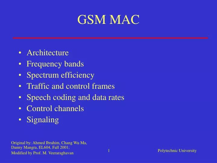
GSM MAC. Original by: Ahmed Ibrahim, Chang Wu Ma, Danny Mangra, EL604, Fall 2001; Modified by Prof. M. Veeraraghavan. Architecture Frequency bands Spectrum efficiency Traffic and control frames Speech coding and data rates Control channels Signaling. Architecture of the GSM network.

E N D
GSM MAC Original by: Ahmed Ibrahim, Chang Wu Ma, Danny Mangra, EL604, Fall 2001; Modified by Prof. M. Veeraraghavan • Architecture • Frequency bands • Spectrum efficiency • Traffic and control frames • Speech coding and data rates • Control channels • Signaling
Frequency bands • Frequency band: Uplink: 890-915 MHz, Downlink: 935-960 MHz • Frequency range: 50 MHz (25 MHz Up, 25 MHz Down) • Carrier spacing: 200 KHz (but time shared bet. 8 subscribers) • Duplex distance: 45 MHz (FDD)
Frequency bands • Number of carriers: 25 MHz/200KHz =124 • Users/carrier: 8 • The reverse channel is retarded by 3 time slots relative to the forward
Frequency bands • One or more carrier frequencies are assigned to each BS • Eight time slots are grouped into a TDMA frame (120/26 ms, or approx. 4.62 ms; 120 frames in a multiframe that is 26ms in duration) • Time slot = 4.62/ 8 ms (or approx. 0.577 ms) • One physical channel is one time slot per TDMA frame.
Conventional carriers • The conventional carrier is a sine wave at a single frequency
Slow frequency hopped carriers • Each TDMA frame in a given channel is carried on a different carrier frequency • The purpose is to reduce co-channel interference between signals in nearby cells • Frequency hopping adds a new dimension of complexity to cellular reuse planning
5 5 5 5 5 5 5 5 5 5 5 5 5 5 5 5 5 5 5 5 5 5 5 5 5 5 5 5 5 5 5 5 5 5 5 5 5 4 4 4 4 4 4 4 4 4 4 4 4 4 4 4 4 4 4 4 4 4 4 4 4 4 4 4 4 4 4 4 4 4 4 4 4 4 6 6 6 6 6 6 6 6 6 6 6 6 6 6 6 6 6 6 6 6 6 6 6 6 6 6 6 6 6 6 6 6 6 6 6 6 6 1 1 1 1 1 1 1 1 1 1 1 1 1 1 1 1 1 1 1 1 1 1 1 1 1 1 1 1 1 1 1 1 1 1 1 1 1 3 3 3 3 3 3 3 3 3 3 3 3 3 3 3 3 3 3 3 3 3 3 3 3 3 3 3 3 3 3 3 3 3 3 3 3 3 7 7 7 7 7 7 7 7 7 7 7 7 7 7 7 7 7 7 7 7 7 7 7 7 7 7 7 7 7 7 7 7 7 7 7 7 7 2 2 2 2 2 2 2 2 2 2 2 2 2 2 2 2 2 2 2 2 2 2 2 2 2 2 2 2 2 2 2 2 2 2 2 2 2 The Cellular Concept • Hexagonally tiled cells • Cannot reuse frequencies in six surrounding cells • Minimum of seven frequency sets is required if N=7 5 4 6 1 3 7 2 • Repeat tiling of seven-cell array • Distance between like cells must be far enough to avoid interference • Smaller cells lead to better frequency reuse • More calls per unit area • Transmitted power must be smaller to avoid interference • Requires careful power management • Requires larger number of base stations
Spectrum efficiency • Assume N =3 (depends on environment) • Country side: N = 2 or 3; • Metropolitan areas: N > 3 or higher Carriers: 124; each carrier has 8 channels: No. of physical channels = 124*8 = 992 Total frequency band: 25(uplink)+25(downlink)=50MHz Efficiency = 992/(3*50MHz) = 6.61 conversations/ cell/ MHz
Traffic channels • A traffic channel (TCH) is used to carry speech and data traffic. • TCHs are defined using a 26-frame multiframe (a group of 26 TDMA frames) • The length of a 26-frame traffic multiframe is 120 ms • Out of the 26 frames, 24 are used for traffic, 1 is used for the Slow Associated Control Channel (SACCH) (12 and 25 on alternate multiframes) and 1 is currently unused.
GSM transmission rate • A full-rate traffic channel has a bit rate of • Within each time slot, some bits reserved for control; only • 114 bits of 156.25 bits are for voice data • Contrast this to IS136 where transmission rate is 48.6kb/s and to the full-rate channel bit rate of 16.2kbps
Speech coding • new: Enhanced Full-Rate (EFR) coding • original: Linear Prediction Coding with Regular Pulse Excitation (LPC-RPE) • coder: 13kbps • with channel coding, rate becomes 22.8kbps – for a full-rate channel
Control channels • Common channels can be accessed both by idle mode and dedicated mode mobiles. • The common channels are used by idle mode mobiles to exchange signaling information required to change to dedicated mode. • Mobiles already in dedicated mode monitor the surrounding base stations for handover and other information. • The common channels are defined within a 51-frame multiframe, so that dedicated mobiles using the 26-frame multiframe TCH structure can still monitor control channels.
Reverse control channel access protocol begin Send message Slotted Aloha Scheme Other transmissions in this slot? yes no no yes Base detects message ? Another message with same 5-bit code? no yes no Max attempts? Access Conflict Access Fails Access Succeeds Random time delay terminal is assigned an SDCCH
Address LI Data Fill Control Messaging • GSM specifies the communication protocols employed on ALL the Network Interfaces • All of the signaling channels (except FCCH, SCH & RACH) transmit information in LAPDm format. • PHY carries these messages in 184-bit segments 184 bits
Functions • Radio Resources Management (RRM) • Controls the setup, maintenance, and termination of channels, including handovers. • Mobility Management (MM) • Manages the location updating and registration procedures, as well as security and authentication. • Call Control Management (CCM) • Handles general call control, similar to CCITT Recommendation Q.931, and manages Supplementary Services and the Short Message Service.
Delivery of a call to a GSM mobile station Mobile Station Base Station Initial Procedure (see slide 33) RACH: “Channel request” AGCH: “Immediate assignment” MSC gets MS’s location I am here. SDCCH: “Paging response” SDCCH message exchange (see Slide 34) SDCCH: “Assignment ACK” FACCH: “Connect ACK” Conversation
Initial procedure in delivery of a call to a GSM mobile station SCH: “Sync Channel Information” Mobile Station Base Station BCCH: “System Information” PCH: “Paging Request” RACH: “Channel request” PCH: Paging Channel Purpose: To notify terminals of arriving calls.
Authentication request Authentication response CIPHERING MODE Ciphering Mode ACK setup Call Confirmed ALERTING CONNECT Assignment Command SDCCH message exchange in delivery of a call to a GSM mobile station Base Station Mobile Station SDCCH: Standalone dedicated control channel
Termination of the call (by MS) How is the call terminated at MS? Mobile Station Base Station Conversation FACCH: “Disconnect” FACCH: “Release” FACCH: “Release complete” FACCH: “Channel release”
References • Wireless Personal Communication Systems, David J. Goodman • Overview of the Global System for Mobile Communications, John Scourias, University of Waterloo • GSM Cellular Standards: A look at the world’s most common digital cellular system, Kevin Bolding, Electrical Engineering, Seattle Pacific University • Wireless and Mobile Network Architectures, Yi Bin Lin, Imrich Chlamtac • Mobile Radio Networking, Networking and Protocols, Bernhard H. Walke