Download
1 / 3
70 likes | 419 Views
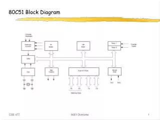
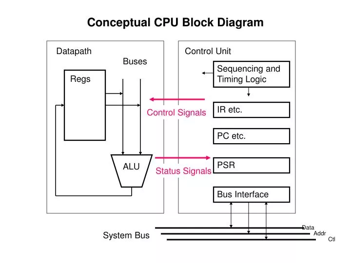
Conceptual CPU Block Diagram. Datapath. Control Unit. Buses. Sequencing and Timing Logic. Regs. IR etc. Control Signals. PC etc. PSR. ALU. Status Signals. Bus Interface. Data. Addr. System Bus. Ctl. Conceptual IR Circuitry. from Data Bus. IR. Control Signals to Datapath.

E N D
Conceptual CPU Block Diagram Datapath Control Unit Buses Sequencing and Timing Logic Regs IR etc. Control Signals PC etc. PSR ALU Status Signals Bus Interface Data Addr System Bus Ctl
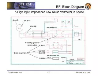
Conceptual IR Circuitry from Data Bus IR Control Signals to Datapath op bits rd rs1 i rs2 to ALU F-bits to C Decoder to A Decoder to B Decoder or op bits rd rs1 i simm13 B decoder enable to B Bus sign ext. or op bits cond disp22 to Branch Control or ...
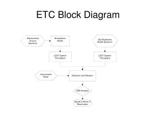
Conceptual PC and PSR Circuitry from IR Status Signals from Datapath Mask and shift from ALU status bits +4 from IR:op, cond MUX PSR (Flags) 32 bit Adder Branch Control PC to Address Bus