Download
1 / 11
110 likes | 117 Views
This document provides recommendations for developing a second-generation CFD mesh for spray G, including specified geometry features and orientation convention. Additionally, it discusses the limitations of X-ray tomography measurements and compares the results to optical microscopy. Technical accomplishments and further analysis are also presented.

E N D
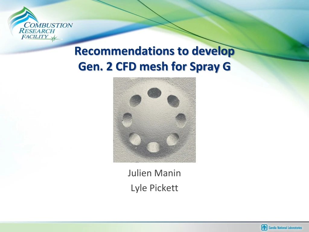
Recommendations to develop Gen. 2 CFD mesh for Spray G Julien Manin Lyle Pickett
List of features “Specified” geometry with “open” pintle/ball 6 10 8 • Inner hole inlet diameter after inlet radius 3 • Inner hole exit diameter before exit radius 4 • Inner hole inlet radius of curvature • Inner hole exit radius of curvature • Inner hole length • Inner hole drill angle relative to injector axis • Outer hole inlet diameter after inlet radius 9 • Outer hole exit diameter before exit radius 10 • Outer hole inlet reverse radius of curvature • Outer hole exit radius of curvature • Outer hole length 9 7 4 3 2 11 1 5
Spray G orientation convention • We decided to use the SAE J2715 as guidelines for the orientation of the Spray G injector (Different from Spray A) • The hole numbering is done clockwise from the front view of the injector (facing the spray tip)
X-ray tomography measurements • Two datasets have been obtained for injector 28 using x-ray tomography measurements: • ESRF – 1.325 µm resolution • Northstar imaging – 5.07 µm resolution – STL • Unfortunately, the data from the ESRF cannot be processed to extract detailed information about internal geometry
Comparison to optical microscopy • Optical microscopy provides relatively accurate measurement of outlet equivalent diameter • But the measurements only consider the very exit of the orifice • Problematic when the orifice is cylindrical or inversely tapered • The optical microscopy measurements show larger quantities than the x-ray-derived STL data • X-ray tomography shows that the minimum hole diameter is slightly smaller than the value measured near the exit
Inner hole mean shows a slight (3 um) divergence once “settled” inside hole to the exit.
Technical Accomplishments Understanding sources of plume-to-plume dispersion and plume-to-plume interaction (Spray G) • Top plumes appear to penetrate more quickly, at least initially • In agreement with atmospheric patternation and imaging performed at Delphi for the same injector (#28) Ambient 15 bar 9 kg/m3 5.8 bar 3.5 kg/m3 Front-View Mie-scatter Spray G
Hole size accounts for some variance between plumes optical microscopy of inner hole • x-ray min. • commercial x-ray tomography • optical
Not much change in outer hole to justify a change from spec.
Further analysis • The radius of curvature at the entrance and exit of the flow orifice is paramount to the flow • The ESRF data reject the specifications in that respect • The Northstar STL is definitely under-resolved to accurately describe these parameters R80 • The Northstar data can be used to extract hole drill angle information • Angles roughly vary from 34 to 39o(specification is 37o) • At the same time, the angle values are highly uncertain because of the short orifice length