Download
1 / 3
30 likes | 115 Views
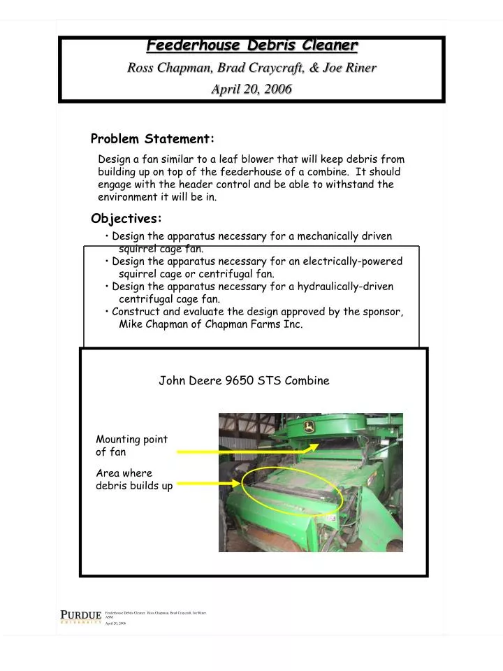
Feederhouse Debris Cleaner. Ross Chapman, Brad Craycraft, Joe Riner. ASM April 20, 2006. Feederhouse Debris Cleaner Ross Chapman, Brad Craycraft, & Joe Riner April 20, 2006. Problem Statement:

E N D
Feederhouse Debris Cleaner. Ross Chapman, Brad Craycraft, Joe Riner. ASM April 20, 2006 Feederhouse Debris Cleaner Ross Chapman, Brad Craycraft, & Joe Riner April 20, 2006 • Problem Statement: • Design a fan similar to a leaf blower that will keep debris from building up on top of the feederhouse of a combine. It should engage with the header control and be able to withstand the environment it will be in. • Objectives: • Design the apparatus necessary for a mechanically driven squirrel cage fan. • Design the apparatus necessary for an electrically-powered squirrel cage or centrifugal fan. • Design the apparatus necessary for a hydraulically-driven centrifugal cage fan. • Construct and evaluate the design approved by the sponsor, Mike Chapman of Chapman Farms Inc. John Deere 9650 STS Combine Mounting point of fan Area where debris builds up
Mechanical Drive Design Criteria • Blower fan with 400 cfm and 200 mph. • Shaft drive, requires ¾ HP @ 3500 RPMs. Complications • No suitable attachment point for the drive pulley. • The fan for this design cost $528. Three Design Options Initial Sketch of Mechanical Drive • Electric Drive Design Criteria • Blower fan with 400 cfm and 200 mph. • Shaft drive, requires 2.5 HP @ 7000 RPMs. • 12V x 22A = 264 Watts • 264 Watts / 746 Watts/HP = 1/3 HP • 8 HP = 1 electric HP • 1/3 * 8 = 2.64 HP Advantages • Motor: $70 • Fan & housing: $0 • Ease of installation Initial Sketch of Electric Drive • Hydraulic Drive Design Criteria • Blower fan with 400 cfm and 200 mph. • Shaft drive, requires ¾ HP @ 3500 RPMs. Complications • Dimensions of fan would not work with the clearance requirements. • The fan for this design cost $528. Initial Sketch of Hydraulic Drive
Chosen Design • Electric Drive • Simple construction and low cost. • Materials used were appropriate because the return value to the sponsor would not justify an expensive solution. • Design can be used on multiple makes and models of combines. • Electric Schematic • The motor is turned on when the header is engaged by means of a relay. • 10 gauge wire is needed to supply the 22 amp load to and from the motor relay. • A 30 amp inline fuse is used between the battery and the relay. • Project Cost • GE Moisture and Dust Proof 12-volt DC motor $70.00 • Fan Blade $15.00 • Fan Blade Housing $30.00 • ProE Drawings $45.00 • Mounting brackets $30.00 • Switch $2.00 • Solenoid/relay $5.00 • Wiring $3.00 • 30 amp circuit breaker $2.00 • Paint $8.00 • Total:$210.00