Download

1 / 19
190 likes | 315 Views
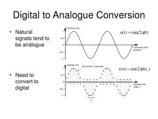
Digital to Analogue Conversion. Chapter 13. Why is conversion needed?. Most signals in the world are analogue. Microprocessors and most computers computers use digital signals.

E N D
Digital to Analogue Conversion Chapter 13
Why is conversion needed? • Most signals in the world are analogue. • Microprocessors and most computers computers use digital signals. • Analogue to Digital Converters (ADCs) change analogue signals to digital signals that are then used by the microprocessor. • Digital to Analogue Converters (DACs) may be used to change digital signals to analogue signals that are then used by the peripherals attached to the microprocessor.
ADCs and DACs • ADCs tend to be more common on a microprocessor. • The number of peripherals that have ADCs and DACs integrated inside is increasing so the microprocessor may not need this capability in the future. • Why? Because more peripherals are manufactured with integrated ADCs. However, you then need to decide type of format that the digitized data will be transferred to your microprocessor • Examples: I2C, CAN, SPI, ethernet, USB
mbed Note: Analogue (UK) and Analog (US) are two different spellings for the same word.
Digital to Analogue Conversion (DAC) Block Diagram • D is the digitalinput. • Vo is the Analogoutput. • Vris aprecise, stable,known voltagereference, • There are somecontrollines that are used to determine how often the DAC should convert the input signal, for example.
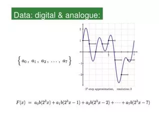
A relatively straightforward DAC can be realised using a resistorA relatively straightforward DAC can be realised using a resistor network,acommontypeis theR-2R ladder Dn-1 Vout– AnalogOut MSB 2R R 2R . . Dn-2 DigitalIn D2 2R R D 1 2R Good test of your knowledge of Thévenin’stheorem,can you showthat: R Do LSB 2R 2R V r (Dn12n1Dn22n2...Do20) Vout 2n
Asimplerelationshipusuallyrelatesthedigitalinputtotheanalogoutput,such as Voisthe analogoutputvoltage Disthe valueofthe binaryinputword nis the number of bits inthe input word Vris the value ofthe voltage reference D Vo nVr 2 Vr(2n-1)Vr/2n(2n-2)Vr/2n 2Vr/2nVr/2n OutputVoltage(Vo) 2n 000 001 010 2n-2 2n-1 D(inputbinarynumber)
Analog Output • There are a finite set of voltages that are generated by the DAC. • Foreachdigitalinputvalue,thereisacorrespondinganalogue output voltage. • Numberofpossibleoutputvoltagesis2n(numberofbitsinthe word) • TherangeoftheDACisthedifferencebetweenthemaximumand minimumoutputvalues. • The resolution of the DAC is the step size between each analog value. • Conversion speed is the inverse of the time that it takes the DAC to act on changes to the input.
MaximumpossibleoutputvalueoccurswhenD=(2n-1). Thevalueof Vrasanoutputisneverreached. (Review the R-2R figure to determine why.)
3 bit DAC in previous example • Maximum number of analog output voltages? • Range of the DAC? • Resolution of DAC?
mbed • TheLPC1768hasa10bitDAC,andusesitsregulated3.3Vpower supplyasthevoltage reference. • What are the number of steps, range, the resolution, the range, and the conversion speedoftheLPC1768DAC? • It takes 5 ms per conversion. • How many clock cycles does this conversion take?
mbed • Thembed’s LPC1768chiphasa 10-bit DAC(i.e.n=10). • Thembeduses itsown 3.3Vpower supplyasvoltage reference. • Therewill thereforebe 2nstepsin thembedDACoutput characteristic,i.e. 1024. • Thestepsize, or resolution,is therefore be3.3/1024, i.e. 3.2mVper bit. • The conversion speed is 200,000/s. The clock speed is 100 MHz so the conversion time is equivalent to 500 clock cycles. • There is another specification called the sampling frequency. The maximum sampling frequency provides a limit to the speed at which the digital signal can be sent to the DAC
It is relatively easilycheckthe resolutionoftheDAC. For example, create an extremelyslowsawtooth. In this case, ittakes10,000stepstoreachthemaxvaluewith a 1 second interval between each step. The period of the waveform is about 2 hours 45minutes, butthisisnotthe point. Note: By the end of this course, you should be able to go through a simple program and describe what each line of code means and what the mbed will do as a result. You should also be able to write a simple program for the mbed .
Measurement • ConnecttheAnalogOutpintoavoltmeter or an oscilloscope. • LEDflasheseach time thatanewanalog valueisoutputtedbytheDAC. • However, 10,000 is larger than the maximum number of steps for the mbed DAC. • So, theDACoutputvoltageonlychangesonapproximately every 5thstep andwhenitdoes,theoutputvoltagechangesby about 3mV. • The float value is roundedtothe nearest digital input tothe DAC.
IdealDAC From Understanding Data Converters, Texas Instruments Application Note
Offset Error From Understanding Data Converters, Texas Instruments Application Note
GainError From Understanding Data Converters, Texas Instruments Application Note
GainError OffsetError NonlinearityError TotalError From Understanding Data Converters, Texas Instruments Application Note