Download
1 / 28
280 likes | 289 Views
Designing and Installing Wireless Ethernet Systems. Wireless Ethernet Radios. The most common questions… Do I need backhaul, multiple access, cellular or mesh? What type of antennas to use? How far will the link go? How does the system handle interference?

E N D
Wireless Ethernet Radios The most common questions… Do I need backhaul, multiple access, cellular or mesh? What type of antennas to use? How far will the link go? How does the system handle interference? How does the data rate change with distance? How is security handled? How to setup an installation? How to install multiple systems in close proximity? What about power supply? What to do about lightning?
What is the difference between backhaul, multiple access and mesh? Backhaul solutions are optimized for fixed point to point connections. Longest range and highest success rates. Fixed Multiple Access solutions are optimized to support several simultaneous device as fixed locations. Great for surveillance applications. Cellular systems are versatile but require monthly fees. They are relatively inexpensive to buy and install. Specialized radios with high quality antennae at elevated locations have best success. Busy populated venues often have throughput issues. Mesh systems require high radio node density. They are relatively expensive to buy and install. Smaller node counts have better success and higher throughputs.
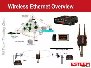
“Backhaul” systems with directional antennae Location #2 17 miles Location #1 Location #3 Main Location Point to Point radios – each subscriber gets a dedicated radio link for maximum throughput.
“Directional antennae” “Sector antennae” Location #4 Location #2 17 miles Location #3 Location #1 Main Location Multipoint radios – data rate is shared between subscriber radios in sector
“Backhaul” systems with directional antennae Location #2 4 miles Location #1 Location #3 Omni Antenna Multipoint radios – data rate is shared between subscriber radios Main Location
1000ft “Portable or Mesh” systems with Omni antennae 1,000ft 1000ft 1,000ft 1,000ft Omni Antenna Multipoint/mesh radios – Data is shared and repeated between subscriber radios Main Location
How far will the radio go? Radio Link Budget – Free Space Loss = System operating margin System operating margin >18dB is safe
Link Budgets At 900Mhz with 15dBi with 2.5dBi + transmitter power 21dB 21dB + transmitter antenna gain 15dB 2.5dBi – transmitter cable losses 0dB 0dB + receiver sensitivity 97dB 97dB + receiver antenna gain 15dB 2.5dBi – receiver cable losses 0dB 0dB ____________________ _____ _____ Link Budget = 148dB 123dB At 5800Mhz with 23dBi with 5dBi + transmitter power 21dB 21dB + transmitter antenna gain 23dBi 5dBi – transmitter cable losses 1dB 0dB + receiver sensitivity 97dB 97dB + receiver antenna gain 23dBi 5dBi – receiver cable losses 1dB 0dB ____________________ _____ _____ Link Budget = 162dB 128dB
Free Space loss Free space loss = 20log(Freq in MHz) + 20log(distance in miles) +36.6 Distance 900MHz: 5800MHz: 0.1 mile has 76dB of loss 92dB of loss 1 mile has 96dB of loss 112dB of loss 10 miles has 116dB of loss 132dB of loss 50 miles has 130dB of loss 146dB of loss
Line of Sight Examples: Will a 5.8Ghz AvaLAN link work at 40 miles using 23dBi panels on both ends? Yes: Link budget (162dB) – Free space loss (144dB) = System operating margin (18dB) Will a 900Mhz AvaLAN link work at 50 miles using a 15dBi yagis on both ends? Yes: Link budget (148dB) – Free space loss (130dB) = System operating margin (18dB) Will a 5.8Ghz AvaLAN link work at 5 miles using a 5dBi omni and a 23dBi panel? Yes: Link budget (145dB) – Free space loss (126dB) = System operating margin (19dB) Will a 5.8Ghz AvaLAN link work at 3/4 mile using 5dBi omnis on both ends? Yes: Link budget (128dB) – Free space loss (109dB) = System operating margin (18dB)
Diffractive Non-line-of-sight Angle of Attack 900Mhz 2.4GHz 5.8GHz 500 ft 10 Degrees 10 Degrees 20ft 20ft 2 Miles Angle of attack Distance 1° 10 Miles 5° 5 Miles 10° 1 Miles
Up to 1500ft Penetrating Non Line of Sight
How does the data rate change with distance? An AW900 systems should only be affected by the added 3% speed of travel delay. An AW58100 systems at a 50 mile link will have a 80% data reduction due to slower coding gain required to achieve distance.
How is security handled? AES keyed encryption – FIPS 197/140-2 Encryption at the application layer is becoming a preferred technique for securing sensitive communications.
Robust against interference? How does the system handle interference? In band and out of band? How easy is the system to intentionally jam? Is the system able to autonomously coexist or is a truck roll required to perform a site survey and change channel ?
How to setup multiple systems in close proximity? Use high gain antennae to isolate and direct energy… For Pt to Pt, Keep the units paired together… Setup one link at a time with the others off… Adjust antennae to create sufficient isolation between links use angular, polarization, spectral and spatial separation…
Isolation techniques Horizontal Polarization Delta Angular Vertical Polarization
Power supply options? AvaLAN offers two power supply accessories. Indoor AW12V - cigarette lighter powered mobile applications. Outdoor AW24V - 24VAC power common in security markets The radios are midspan POE powered from 12VDC to 48VDC. For solar applications it is possible to power the AW900 radio in continuous transmit with 12VDC at 120mA = 1.5 Watts of power draw. For solar applications it is possible to power the AW58100 radio in continuous transmit with 12VDC at 500mA = 6 Watts of power draw.
How to provide lightning protection? AvaLAN’s antennae are DC grounded. However, the use of inline lightning suppressor is always a good idea. Mount the antenna at least 3ft from the top of a grounded pole
Thank you! www.AvaLANwireless.com Sales - sales@AvaLANwireless.com (866)533-6216 Support - support@AvaLANwireless.com (650)384-0000