Download
1 / 30
320 likes | 339 Views
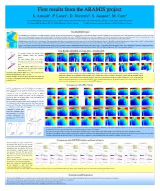
AraMiS Star Tracker Design. Diego Urbina. Star Trackers. Star Trackers measure the stellar coordinates and compare them with previous images or a database of stars stored on board. This results in an attitude mea-

E N D
AraMiS Star Tracker Design Diego Urbina
Star Trackers Star Trackers measure the stellar coordinates and compare them with previous images or a database of stars stored on board. This results in an attitude mea- surement of the star tracker with respect to the celestial sphere, which can then be translated to the attitude of the spacecraft. EADS Sodern SED16 Star Tracker on board the ATV Jules Verne AraMiS Star Tracker block scheme, with its two units, the Star Tracker Processing Unit and the Star Tracker Camera Unit
State of the art Attitude sensors come in a wide variety of types. The sensor used in any specific mission depends largely on the characteristics of the mission, and must achieve a balance between accuracy, size, computational power and FOV constraints IR Earth • Expected accuracy of the AraMiS sun sensor ~ 0.5 deg Sun sensor Magnetometer Images: NASA, JPL, Technical University of Denmark
State of the art (2) Second Gen example: AA-STR Star Tracker from Galileo Avionica • CCD-based (superb sensor performance, low noise, but increased size and weight) • Embedded catalogues and algorithms • Up to 10 tracked stars • Op. Modes: LIS (Lost in Space) and Tracking Mode • FOV:16.4 deg. • Roll rate: 0.5 deg/sec at full accuracy2 deg/sec at reduced accuracy • Bias error: <10 arcsec • Low freq. error: <7 arcsec pitch & yaw <25 arcsec roll • Random error at 0.5 deg/sec <9 arcsec pitch & yaw <95arsec roll • Random error at 2deg/sec: <20 arcsec pitch & yaw <210 arcec roll Image: Selex/Galileo Avionica Mass: 3 kg with baffle (heavy for a microsatellite!) Size: 195(L)x175(W)x288(H) mm (huge for a microsatellite) • Op Temp: -30 to +60 deg C • Power cons. 8.9 W and more, if the temperature rises (probably due to the peltier cooling system) Expected accuracy for AraMis (Third generation Star Tracker) ~ 200 arcsec (at low roll rates)
A note on reference systems Precession: there is a precession of the poles with a duration of 26000 years, that is, every object in sky moves 0.014 degree to the east every year. Right now, the north pole points very near to the star Polaris. Nutation: a small nodding motion with a period of 18.5 years and amplitude of 9.5 arc sec Chandler Motion: A short-period change of the poles, but a pretty small one (some milliarc sec). Image: JPL How do we take this effects into account? -We use Epochs We “pin down” every object on the Celestial Sphere to its coordinates in a certain moment, that “averages” its position during the epoch. We are currently in Epoch J2000, which is the one our catalogues and algorithms will be based on. What’s a Celestial Sphere anyway?
A note on reference systems (2) The Celestial Sphere is a sphere of infinite radius. Its poles coincide with earth’s poles and with the equator line, but not with the ecliptic plane (the plane on which earth orbits the sun). The celestial equator shows an inclination of 23.4° respect to the ecliptic plane, for J2000. The position of every object in the sky, including stars, can be described by a Right Ascension (RA) and a Declination (DEC). The origin of this frame of ref. is in the Vernal Equinox or First Point of Aries. DEC: +90° (N pole) to -90° (S pole) RA: 0 to 24 hours (the sky rotates at 15°/h, 360°/24=15°)
Some pattern matching techniques (1) Simple Only one search needed Needs almost perfect noise rejection. Stars with a similar magnitude appear almost the same to a non ideal sensor. Absolutely impractical. Single Star matching: Identify one star, compare to the magnitude of all the catalogue stars Little computationally demanding 10 stars must be seen at any time in the FOV, and at least 7 stars need to be matched to properly identify the pattern. Grid pattern matching: (Hyunjae, Choong-Suk, Hyochoong 2003) Angle pattern matching: Considerable memory requirements In practice, many more than three stars are needed (pivoting) Comparatively slow Theoretically, only two stars needed
Some pattern matching techniques (2) Fast Very computationally demanding Considerable memory requirements Spherical Triangle Matching: (Cole, Crassidis 2004) Identify three stars, get the area and moment of the spherical triangle that is formed. Compare with a database of triangle areas and moments. Considerable memory requirements Planar Triangle Matching: (Cole, Crassidis 2005) Identify three stars, get the area and moment of the planar triangle that is formed. Compare with a database of triangle areas and moments. Fast Less calculation load on the DSP Planar triangle matching is the technique of choice for the AraMiS Star Tracker
Star Catalogue compilation The Yale Bright Star Catalogue, is a star catalogue that lists of all stars of stellar magnitude 6.5 or brighter (the lower the number, the brighter), which is more or less every star visible to the naked eye. It lists, among lots of other data: • Some brightness values: • −26.73 Sun • −1.47 Brightest star, Sirius • 0 The zero point by definition: it used to be Vega • 6.5 Faintest stars observable with naked eye under perfect conditions The YBSC contains 9110 objects of which of which 9096 are stars. We eliminate this residual objects (Novae, extragalactic objects). We then scan the whole celestial sphere in small, 1° steps and leave only the 5 most brilliant stars per FOV. This value was chosen to maximize the known stars while keeping the database from growing too much. We also unite stars that are too near for a sensor to distinguish.
Star Catalogue compilation The first stage of compilation results in a 1959 star list, with i,j,k values, that describe the unitary vector pointing to a star. It also provides a visual magnitude value. Since direct indexing instead of searching will be well appreciated by the SW running in the sensor, the algorithm also gives out a 9110 position-long LUT integer vector, whose index is the HRN and whose content is the index into the aforementioned vectors. • Note: A compiled catalogue for a specific FOV can be used efficiently only by a sensor with that very FOV. Changes in the simulation optics, or the hardware optics must follow a re-compilation of the stars.
Star Catalogue compilation • The second part of the compilation involves the generation of the values that will be used to identify stellar patterns. • Every possible star triplet that fits in the FOV is analyzed, and two values are calculated out of the three unitary vectors of the three stars: • Area of the planar triangle (using heron’s Formula): • Polar Moment of the planar triangle: where The software generates a list of all the possible triplets, which for a FOV of 21° 32’ 4.7’’ and 5 stars per FOV, consists of 265.292 elements, each with its Area, Moment, and three HRNs,
Simulation platform Celestia is a highly customizable 3D astronomy application (GNU GPL), based on the ESA Hipparcos catalogue of planets, moons, asteroids, comets, artificial satellites, spacecraft; and finally almost 120000 stars, of which we use about 9000. It has a scripting language based on the LUA language, which allows to freely move around and rotate, set up the FOV, star visibility and also program the necessary calculations to get a visual output of the attitude in quaternions or euler angles. Appropriate screenshots and motion scenes were taken to feed the algorithm. Google Earth (Freeware) and MS Worldwide telescope (Freeware) were used to support “human” visualization and manual star search.
Simulation platform (2) A sequence of images is created on Celestia, with all the conditions set to what an average imager in LEO is sensitive to (no atmosphere, no nebulae, and naturally, no object, orbit, and various different default tags from the software).
Pattern ID method A star on the sensor has the shape of an Airy’s Disc, which is approximable to a gaussian function up to the first zero. Our goal at a first stage will be obtaining the center of the star, that should be the center of this gaussian function. The signal, however, is affected by different types of noise (signal shot, dark current, BG noise, Quantization noise, readout noise), whose variances can be conveniently added to form the variance of the total noise electrons on the sensor. This noise is inerted into the simulated image. Detail of a simulated star with added noise
Pattern ID method (2) Thresholding The average pixel value of the last 5 images captured by the sensor provides a decent reference of the noise level. A threshold is calculated from it (we use twice the value of the noise level), and all the pixels with a lower value are taken out. This is an actual mask used to remove the aforementioned pixels. White pixels are potential star pixels. We notice the presence of the stars, and also of residual noise spikes that exceeded the threshold.
Pattern ID method (3) To remove the spikes, the whole image is scanned with a 5x5 pixel window. If more than half of the pixels in the window are above the threshold, all the pixels in the window are deemed valid, otherwise, they are noise peaks. This is the mask produced in order to remove the noise peaks. White pixels are those considered valid star pixels. A segmentation algorithm that groups the pixels belonging to each star is run on this mask.
Pattern ID method (4) Centroiding After applying the mask to the image, valid star pixels are used to calculate the center of the star, using the weighted sum technique. Note that this allows to know the position of the center of the star with subpixel precision. Posizione=position x,y on the image NumFotoni(i)=number of photons in pixel i Posizione(i)=position of pixel i n=number of pixels of the star ppx and ppy are the x and y pixel pitches of the sensor. f is the focal length of the lens. X and y, the star positions. The centers are used to get a set of unitary vectors pointing to the stars, in the local (imager) frame of reference.
Centroiding performance Centroid testing on actual pictures:
Centroiding performance Centroid testing on actual pictures:
Centroiding performance Centroid testing on actual pictures:
Pattern ID method (5) The planar triangle formed by the three unitary vectors of the 3 brightest stars is analyzed, and an area and moment are calculated with the same formulae used in the compilation of the catalogue.
Pattern ID method (6) We can go now and look for the triangle in the triangle list. But conventional (linear, binary) search methods are a bad idea for this amount of data.. When ordered, areas or moments closely resemble a parabola. For both of them, we can determine the formula of the parabola that aproximates the graph. Solve the equation for value ta (measured), get a, which is an index into vector B. Vector B holds the true index of the element (i) into the triangle list. ta a i i
Pattern ID method (7) The search is performed and we get the triangles over an interval of 3*sigma, with sigma being the standard deviation of the area or moment measurements. This returns a list of a few thousand triangles. Pivoting We then take two of the stars of the triangle and repeat the process with a 4th external star, filtering out the triangles that don’t have 2 stars in common with this new list. We do this twice, max (the catalog “knows” 5 stars x FOV). Now there are 3 possibilities: we find it (positive ID), we don’t, or we run out of pivots (inconclusive result). Preliminary results (Lost in Space): 60% of unique “correct” measurements.
Pattern ID with an a priori reference We may have a reference that comes from the AraMiS sun sensor, which provides an attitude vector with two degrees of freedom. In compilation stage, a module was added, that created a spheroid based on an 320-face polyhedron, to geographically divide the sphere into little zones, much like the Buckminster Fuller “Dymaxion map”, except with more faces, and the celestial sphere, instead of the earth. The centroid of every triplet is located in one of the faces, and the triplet is tagged with the face number. Buckminster Fuller “Dymaxion map” We will search for triangles that are, only in the face that the sun sensor says we point to, and on the adjacent faces. This reduces the local candidate triangles for each search from 265 292 to about 10 thousand.
Current performance 17% of the time, the algorithm reaches an unique and correct solution. Therefore, to get 17 attitude readings, 100 photoshots should be taken. Wrong results are identifyed on board, and filtered out. By increasing the number of known stars, more pivoting steps can be effectuated In order to aumentate the throughput, tests are now being made on 6 stars x FOV and 8 stars x FOV databases. Time performance (seconds vs frames): Mean: 1.527 secs/frame (MATLAB on Intel Pentium dual core 1.80 GHz) Average: 8.9 secs per single attitude reading (+ image integration time).
Rotation representation • Direction Cosine Matrix:9 parameters, each one is the cosine of the angle between a rotated unit basis vector and one of the reference axes. • Euler Angles: 3 parameters, each one is the single rotation about each axis (roll, pich, yaw). • Quaternions: • More compact than DCMs • Vary continously. • It’s simple to combine rotations through quaternion products
Attitude determination Attitude estimation is done through Wahba’s Loss function. V(k) are the database vectors, W(k) are the observed vectors, a(k) are weights assigned to each observed vector, and A is the matrix to be found, which minimizes Wahba’s function. Paul Davenport gave one solution to Wahba’s cost problem by proposing a matrix B (Davenport’s Attitude Profile Matrix) And if one defines: and , which is the quaternion equivalent of A, must satisfy: Where lambda(max) is the maximum eigenvalue of K. By solving numerically the equation of the characteristic polynomial of K, we obtain the attitude quaternion.
Attitude determination (2) The attitude quaternion is then rotated to the main local reference frame of AraMiS (the local imager frame shall be tilted to protect it from the sun). The resultant quaternion qw, q1, q2, q3 is then sent over the bus, along with the exact time the shot was taken.
HW: Optics choice • Pinhole • Single Lens • Double Gauss Lens Field curvature