Download
1 / 31
310 likes | 443 Views
VERSITILE COMMUNICAION BETWEEN MULTI DSPS Digital Systems Laboratory Spring 2003. Final Presentation. Presenting: Yaron Yagoda Kobi Cohen. Supervisor: Isaschar Walter. Motivation. Communication Center. VERSITILE COMMUNICAION BETWEEN MULTI DSPS. Introduction System Specifications

E N D
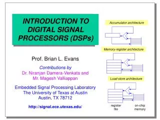
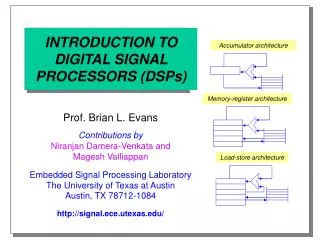
VERSITILE COMMUNICAION BETWEEN MULTI DSPSDigital Systems LaboratorySpring 2003 Final Presentation Presenting: Yaron Yagoda Kobi Cohen Supervisor: Isaschar Walter
Motivation Communication Center
VERSITILE COMMUNICAION BETWEEN MULTI DSPS • Introduction • System Specifications • Project Structure • Router • Protocol • Conclusion
Project Goals Adjusting hardware architecture according to specific signal processing software dataflow. Designing and implementing a flexible, dynamic topology of communication (using the McBSP Protocol) between several DSPs and a PC.
Problem Description DSP DSP DSP DSP Hardware complexity of O(N^2)
The Solution -DRIVER ALTERA FLEX 10KE DSP DSP Switch Matrix + Router PCI BUS DSP PCI CORE DSP
VERSITILE COMMUNICAION BETWEEN MULTI DSPS • Introduction • System Specifications • Project Structure • Router • Protocol • Conclusion
VERSITILE COMMUNICAION BETWEEN MULTI DSPS • Introduction • System Specifications • Project Structure • Router • Protocol • Conclusion
Block Diagram ALTERA DSP FPGA DSP PCI BUS PCICORE DSP DSP McBSP PROTOCOL
Block Diagram )for pipelined connection) ALTERA DSP FPGA DSP PCI BUS PCICORE DSP DSP McBSP PROTOCOL
FPGA Structure DSP DSP Router Matrix Communication Unit Communication Unit Communication Unit Communication Unit DSP DSP
The Matrix Block Controller FIFO Block Controller FIFO Block Controller FIFO Block Controller FIFO
The Communication Unit This unit is responsible to receive data (including the Command Word) from the DSP, ask for a FIFO allocation and when succeed in allocating a FIFO, it transfer the data to the target.
VERSITILE COMMUNICAION BETWEEN MULTI DSPS • Introduction • System Specifications • Project Structure • The Router • Protocol • Conclusion
The Router Reminder: The Router is responsible for allocating the FIFOs to the DSPs (through the communication units) according to the priority and the availability of the FIFOs. Router Matrix Communication Unit Communication Unit Communication Unit Communication Unit
Priority There are 4 degrees of priority,one for each of the 4 FIFOS. The highest is 0 and the lowest is 3. The priority is determined by the PC user. Each port is allowed to write to a FIFO which is equal or higher than its priority.
FIFO Decision After checking the priority of the port, the router checks if there is enough space in the FIFO with the highest priority possible and if there is no room it moves to the next one… In case the amount of words that sends is more than the amount of words in the emptiest FIFO it sends how many words can be received.
VERSITILE COMMUNICAION BETWEEN MULTI DSPS • Introduction • System Specifications • Project Structure • Router • Protocol • Conclusion
Control Word 4 bits 4 bits 8 bits 4 bits 12 bits Source Target Num words Index Reserved Source-The address of the sender. Target-The address of the target. Num words-Number of words in the block. Index-The number of block in the message. Reserved.
Data Receive Flow DSP sends control word Priority Check FIFO Decision Enough space in FIFO? No Yes Limited Space Router send OK word Router send WAIT word Send amount of words can be accepted
McBSP Pin Description Pin I/O Description CLKR O Receive clock CLKX O Transmit clock DR I Received serial data DX O Transmitted serial data FSR I Receive frame synchronization FSX O Transmit frame synchronization
Code Composer CCS is a software integrated development environment (IDE) for building and debugging programs for the DSK (DSP Starter Kit), meaning the DSP board.
WINDRIVER The WinDriver software is the way to communicate between the PC and the project implemented on the FPGA.
The GUI The GUI gives the user an easy way to configure the Matrix. Through the GUI the user can define the priority of each DSP. The GUI allows passing data to each one of the DSPs through the driver. In the GUI we have 4 DSPs, the source address, number of words he wants to send and the destination address. The GUI gives us the option to write or read data to the configured DSP .
VERSITILE COMMUNICAION BETWEEN MULTI DSPS • Introduction • System Specifications • Project Structure • Router • Protocol • Conclusion
Conclusions • In order to adjust our project to the size of the FPGA we had to decrease the size of our project. • A much deeper understanding of the DSP side was needed.
Future Work • Writing a driver to connect the GUI to the FPGA. • Working on a better UI to the DSP programmer(using CCS).