Download
1 / 22
230 likes | 377 Views
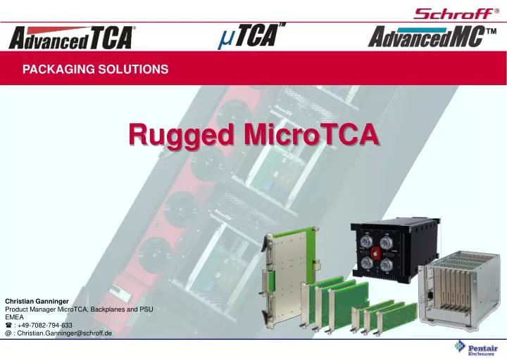
PACKAGING SOLUTIONS. Rugged MicroTCA. Christian Ganninger Product Manager MicroTCA, Backplanes and PSU EMEA : +49-7082-794-633 @ : Christian.Ganninger@schroff.de. Agenda Rugged MicroTCA: Introduction, explanation of MicroTCA.1 & MicroTCA.3, Statusupdate

E N D
PACKAGING SOLUTIONS Rugged MicroTCA Christian GanningerProduct Manager MicroTCA, Backplanes and PSU EMEA : +49-7082-794-633@ : Christian.Ganninger@schroff.de
Agenda Rugged MicroTCA: Introduction, explanation of MicroTCA.1 & MicroTCA.3, Statusupdate Presented by Christian Ganninger, Schroff GmbH Rugged MicroTCA Connector tests Presented by Michael Burger, ept Gmbh & Co. KG Rugged MicroTCA Applications Presented by Irene Hahner, Kontron AG
MicroTCA.0(Micro Telecommunications Computing Architecture Base Specification) MicroTCA.0 as defined provides support for requirements such as NEBS, ETSI and ITU specifications, which are focused on the central office telecommunication environment. Shock & Vibration requirements:
Rugged MicroTCA The Rugged Micro Telecommunications Computing Architecture specifications defines the requirements for a System that meets more stringent levels and cycles of temperature, shock, vibration, and humidity than those defined in MicroTCA.0. MicroTCA.1 (Air Cooled Rugged MicroTCA): this first sub-specification of MicroTCA describes rugged air-cooled systems for industrial applications. Adopted 19-Mar-09 MicroTCA.2 (Hardened Air Cooled MicroTCA): the second sub-specification of MicroTCA; it describes rugged air-cooled systems for military applications. Not started MicroTCA.3 (Hardened Conduction Cooled MicroTCA): the third sub-specification of MicroTCA; it describes rugged conduction-cooled systems for military applications In work
MicroTCA.1 (Air Cooled Rugged MicroTCA) Shock & Vibration requirements : XR1: Vibration3gSinusoidal (MicroTCA.0 = 0,5g)(2-9 Hz, amplitude 10 mm, 9-200 Hz, acceleration 30 m/s², 1 octave/min, 3 axes / 10 cycles each axis) Shock 25g(MicroTCA.0 = 7g)(250 m/s² / 18 ms half-sine, 3 axes, 3 shocks, two directions each axis (18 shocks) In accordance to IEC 61587-1:2007 Performance level DL3 XR2: Vibration 8g Random (5-2000 Hz, 0.04 g²/Hz, 3x1h) In accordance to VITA 47 Class V2 Shock 25g(250 m/s² / 18 ms half-sine, 3 axes, 3 shocks, two directions each axis (18 shocks)) In accordance to IEC 61587-1:2007 Performance level DL3 Resistance shall not increase more than 10 Ohms for longer than 10 ns per contact pair. See GR-1217-CORE section 5.4.4, objective O5-81
MicroTCA.1 (Air Cooled Rugged MicroTCA) Thermal requirements : 3 different Levels: Ambient(MicroTCA.0) and 2 Extended Temperature rangesXT1 & XT1L MicroTCA.0:- 5°C to + 55°C XT1L:- 40°C to + 55°C XT1:- 40°C to + 70°C -> actions: Electronic parts with enhanced temperature range, System cooling has to be adopted Additional requirements: Drop test, RoHS, Acoustic, Surface temperature are defined as application specific For other requirements like Earthquake, Flammability, Atmospheric, Module insertion cycles, ESD, EMC, Safety MicroTCA.1 refers to the MicroTCA.0 base specification
MicroTCA.1 (Air Cooled Rugged MicroTCA) Shock & Vibration requirements : Additional Retention Device mandatory Additional Retention Device mandatory Rugged MicroTCA Retention Device
MicroTCA.1front panel( XR2 ) AdvancedMC.0front panel additionalretentionscrew front panel with flange MicroTCA.1 (Air Cooled Rugged MicroTCA) Rugged MicroTCA Retention Device
MicroTCA.1 (Air Cooled Rugged MicroTCA) Why is a special Retention Device needed? 0,0mm min. 1,6mm max. Gap between Faceplate / attachment planedue to tolerances of the module and the subrack
MicroTCA.1 (Air Cooled Rugged MicroTCA) Why is a special Retention Device needed? Rugged AdvancedMC Module Standard AdvancedMC Module Is plugged into the slot until the module is seated on the bottom of the backplane connector body Inserted into the slot until the module is seated on the bottom plate of the backplane connector Fixed in this position by the locking mechanism of the handle. Fixed in this position by the locking mechanism of the handle. Gap between the front panel flange and the subrack, worst case: 1.6 mm
MicroTCA.1 (Air Cooled Rugged MicroTCA) Why is the Retention Device needed? Face plate deflection When the Rugged MicroTCA Module is screwed to the subrack… F … the face plate will be deflected… … and the force will be applied to the connector. The module bare board and the connector bottom side will be stressed. F Conclusion: A locking method is needed, that fixes the module in the chassis in position without applying force into direction of the connector. F
MicroTCA.1 (Air Cooled Rugged MicroTCA) Solution (patented, part of the MicroTCA.1 specification): Maximum gap ( 1.60 mm )* Gap 0.0 mm µTCA chassis Front panel flange µTCA chassis Front panel flange 1.60 Collet * Based on 185,85 subrack depth Welded sleeve Screw M3
MicroTCA.1 (Air Cooled Rugged MicroTCA) Solution for Rugged MicroTCA & AdvancedTCA Easily exchangeable! Only the stainless steel front panel is different from a standard AMC.0 module. Bare board, die cast parts and handle are the same. With a special Rugged AdvancedMC Carrier the MicroTCA.1 Modules can also be used in a AdvancedTCA environment
0.5; 1.0; 1.5 MicroTCA.1 (Air Cooled Rugged MicroTCA) Verifications: Test 1: Force effect to backplane and connector cont. IssueTest to determine if loads are transferred through the AMC Module PCB to the chassis backplane and connector when fixing an AMC module with the SCHROFF supplemental RµTCA screw fastener in a µTCA chassis. TestScrew fasteners tightened using a torque screwdriver to the DIN prescribed 0,67Nm (for an M3 screw). Three front panel flange to chassis distances were tested: 0.5mm, 1.0mm and 1.5mm. The measurement was repeated for the three distances, a minimum of five times each. Result:Force max. = 1,3 N
Face plate deflection F Force in N 175 100 0.14 0.1 0.2 Face plate deflection in mm MicroTCA.1 (Air Cooled Rugged MicroTCA) Verifications: Test 2: Face plate stiffeness cont. Result
MicroTCA.1 (Air Cooled Rugged MicroTCA) Verifications: Test 3: Shock and Vibration Test Jig for Multiple Slots (3 x Mid-size AdvancedMC.0 Double Modules) Backplane with ConCardMicroTCA connectors AdvancedMC.0Mid-size Module, Double height, 700g Standard Schroff MTCA.0 guide rails and die-cast latch retainer Result: Passed!(Electrically and mechanically)
MicroTCA.3 (Hardened Conduction Cooled MicroTCA) Shock & Vibration requirements : Test 1: Random vibration - 50 Hz to 100 Hz increasing at 6 dB/octave - 100 Hz to 1000 Hz PSD = 0.2 g²/Hz - 1000 Hz to 2000 Hz decreasing at 6 dB/octave - 3 axis each axis 60 mins No contact discontinuity exceeding 10Ω/10 ns Mechanical shock - 40g/11 ms half sine - 3 axis/two directions each 3 shocks No contact discontinuity exceeding 10 Ω/10 ns Test 2: Random vibration - 50 Hz to 100 Hz increasing at 6 dB/octave - 100 Hz to 1000 Hz PSD = 1.5g²/Hz - 1000 Hz to 2000 Hz decreasing at 6 dB/octave - 3 axis each axis 60 mins No contact discontinuity exceeding 10Ω/10 ns Mechanical shock - 50g/11 ms half sine - 3 axis/two directions each 3 shocks No contact discontinuity exceeding 10 Ω/10 ns preliminary
MicroTCA.3 (Hardened Conduction Cooled MicroTCA) Demands other kind of chassis The AdvancedMC Module must be secured with a Wedge-LOK to the chassis The Wedge-LOK has two tasks: - Securing the AdvancedMC module in extreme conditions - Transfering the heat from the hot spots to the outer side of the chassis
MicroTCA.3 (Hardened Conduction Cooled MicroTCA) Intention is: don‘t change the AMC module The module will be inserted into a clamshell The Clamshell will be special for the different AdvancedMC modules The Clamshell will contect the hot spots (with thermal paste)
MicroTCA.3 (Hardened Conduction Cooled MicroTCA) Intention is: don‘t change the AMC module The module will be inserted into a clamshell The Clamshell will be special for the different AdvancedMC modules The Clamshell will contect the hot spots (with thermal paste) Heat transfer will be from the hot spot through the clampshell and the Wedge-LOK to the chassis The chassis might have heat sinks, cold plates or forced air cooling.
MicroTCA.3 (Hardened Conduction Cooled MicroTCA) Status: The PICMG is planing shock & vibrational tests to proof this concept!!!
Rugged MicroTCA PACKAGING SOLUTIONS Rugged MicroTCA Thank you for your attention! Christian GanningerProduct Manager MicroTCA, Backplanes and PSU EMEA : +49-7082-794-633@ : Christian.Ganninger@schroff.de