Download
1 / 36
370 likes | 576 Views
MODIS Calibration, Geolocation and Production. EOS Snow and Ice Workshop November 15, 2004 Robert Wolfe NASA GSFC Code 922 & Raytheon TSC. Outline. Calibration and Characterization Geolocation MODIS Land Production. Outline. Calibration and Characterization

E N D
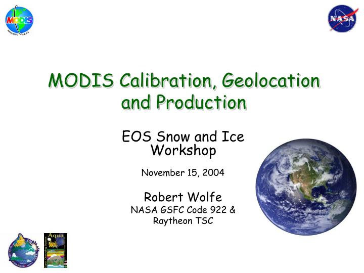
MODIS Calibration, Geolocation and Production EOS Snow and Ice Workshop November 15, 2004 Robert Wolfe NASA GSFC Code 922 & Raytheon TSC
Outline • Calibration and Characterization • Geolocation • MODIS Land Production
Outline • Calibration and Characterization • original slides by Jack Xiong (MODIS Calibration Support Team) • Geolocation • MODIS Land Production
Instrument Overview (1/6) • The MODerate Resolution Imaging Spectroradiometer (MODIS) is one of the key instruments for NASA’s Earth Observing System (EOS), built by Raytheon Santa Barbara Remote Sensing (SBRS) • MODIS ProtoFlight Model (PFM) was launched on board Terra spacecraft on 12/28/99 (first light on 02/24/00). http://terra.nasa.gov/ • MODIS Flight Model 1 (FM1) on Aqua spacecraft was launched on 05/04/02 (first light on 06/24/02) http://eos-pm.gsfc.nasa.gov/ • 20 Reflective Solar Bands (RSB): 0.4 - 2.2 microns • 16 Thermal Emissive Bands (TEB) 3.5 - 14.5 microns
LWIR S/MWIR VIS NIR 1 1 1 1 0 14000 16000 6000 8000 10000 12000 0 0 0 5000 1000 2000 3000 4000 1100 600 600 700 800 900 1000 350 400 450 500 550 Instrument Overview SRCA • 36 spectral bands (490 detectors) cover wavelength range from 0.4 to 14.5 mm • Spatial resolution at nadir: 250m (2 bands), 500m (5 bands) and 1000m • 4 FPAs: VIS, NIR, SMIR, LWIR • On-Board Calibrators: SD/SDSM, SRCA, and BB (plus space view) • 12 bit (0-4095) dynamic range • 2-sided Paddle Wheel Scan Mirror scans 2330 km swath in 1.47 sec • Day data rate = 10.6 Mbps; night data rate = 3.3 Mbps (100% duty cycle, 50% day and 50% night) Solar Diffuser Blackbody Velocity Space View Port Fold Mirror Nadir
On-board Calibrators • SD – Solar Diffuser for RSB calibration, SD BRDF determined from pre-launch, referenced to a transfer standard calibrated at NIST • SDSM – Solar Diffuser Stability Monitor for tracking SD degradation • BB – Blackbody (12 thermistors reference to NIST standard) for TEB calibration. Emissivity determined from pre-launch calibration using a blackbody calibration source. • SRCA – Spectroradiometric Calibration Assembly for spectral and spatial characterization SD SDSM SRCA BB
L1B Collection 5 changes • Terra: • Use deep space maneuver measured Response Verses Scan Angle (RVS) for Thermal Bands • Refit SD/SRCS/Moon trending to derive RVS for Reflective Bands • Aqua: • m1 and RVS will be fitted with consistent data over 2 years
Outline • Calibration and Characterization • Geolocation • MODIS Land Production
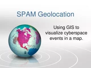
MODIS Geolocation • Geolocation accuracy specification is 150 m (1 σ) and goal is 50 m (1 σ) at nadir • Geolocation goal driven by Land 250 m change product requirements • MODIS is a moderate resolution whisk-broom sensor with 36 spectral bands; 2 at 250 m, 5 at 500 m and 29 at 1 km nadir spatial resolution • “Ideal” band is geolocated • 250m band 1 (645 nm, “red”)
MODIS Scanning Geometry (distance exaggerated in track direction)
Updated Ground Control Points (GCPs) Image chips from Landsat TM/ETM scenes 366 old chips (blue)51 chips removed (red)990 new chips (green)
Geolocation Collection 4 (C4) results Aqua Terra • Good results – RMS error is better than goal in track direction but slightly over goal in scan direction (but much better than specification – 150 m) • Early post-launch coordinate system issue resolved before C4 • Definitive ephemeris is used for best results – causes up to 24 hr processing delay • Excellent results – Root Mean Square (RMS) error in nadir equivalent units is better than accuracy goal • Small remaining northern/ southern hemisphere difference • Large errors occur after orbit maneuvers (about 6 per year) • accuracy in following orbit suspect
Geolocation Collection 5 (C5) changes • Incorporate new Shuttle Radar Terrain Mission (SRTM) Digital Elevation Model data and incorporate • Incorporate new land/water mask from Boston University • Set new flag (GeoloctionAccuracySuspect) identifying times near/after maneuvers • Correct northern/southern hemisphere differences
Outline • Calibration and Characterization • Geolocation • MODIS Land Production
Midwest Snow Dec. 25, 2002 Source: MODIS Land Rapid Response
MODIS Land Products Energy Balance Product Suite • Surface Reflectance • Land Surface Temperature, Emmisivity • BRDF/Albedo • Snow cover/Sea-ice extent Vegetation Parameters Suite • Vegetation Indices • LAI/FPAR • GPP/NPP Land Cover/Land Use Suite • Land Cover/Vegetation Dynamics • Vegetation Continuous Fields • Vegetation Cover Change • Fire and Burned Area
Science Team • Original team formed 12 years ago; team recompeted last year • 3 Disciplines: Land, Oceans, Atmosphere • Responsibilities: • Algorithm Theoretical Basis Document • Algorithms in Software: PGEs (Product Generation Executables) • QA and Validation • Support Groups • Science Data Support Team (SDST) • includes: Discipline Support Groups (Coordination) • MODIS Calibration Support Team (MCST) • includes: MODIS Flight Operations
MODIS Land Science Team – Phase 2 • Overall – Phase 1 Land Team intact and strengthened • Separate funding for Validation Coordination and Rapid Response • Larger Science Team (27 total) • Algorithm Maintenance and Validation Team (10) • EOS Science – Data Users (17) • Four new/improved Land products: Plant Water Content, Evaporation, Improved Surface Reflectance, Physical Based Continuous Fields and Land Cover • Phase 2 approach: • Continue and expand on what has worked (a proactive land group) • Discontinue what didn’t - • Try some new things – within budget – looking for new ideas from new and old team members (from Justice)
Input Data Calibrated Radiance Geolocation Fields Cloud Mask Aerosol Precipitable Water DAO Data Previous Period’s BRDF/Albedo Land Surface Temp./Emissivity Land Cover L2/L2G Products Snow/Sea-Ice Cover Surface Reflectance Fire Land Surface Temp./Emissivity Grid Pointer Data Grid Angular Data Previous L3/L4 Products L3/L4 Products Snow/Sea-ice Cover Surface Reflectance Land Surface Temp./Emissivity Fire and Burned Areas Vegetation Indexes BRDF/Albedo LAI/FPAR GPP/NPP Land Cover and Vegetation Dynamics Vegetation Cover Change and Continuous Fields Evaporation Land Algorithm Dependency
Validation “hierarchy” Definitions • Stage 1 Validation – Product accuracy has been estimated using a small number of independent measurements from selected locations and time periods. • Stage 2 Validation – Product accuracy has been assessed by a number of independent measurements, at a number of locations or times representative of the range of conditions portrayed by the product e.g. EOS Land Validation Core Sites, Fluxnet sites, Aeronet sites. • Stage 3 Validation - Product accuracy has been assessed by independent measurements in a systematic and statistically robust way representing global conditions e.g. IGBP DISCover Project – suggest that this be undertaken • Validation results must be published and appropriate data available All Land products validated to Stage 1 – some products Stage 2 Validated
Product Format • Hierarchical Data Format (HDF) – Self describing file format • Science Data Sets (SDSs) – 2D, 3D or 4D arrays • Bit Fields – unsigned integers broken into groups of bits • Discrete values – e.g., Snow, Cloud, etc. • Scaled Integers – valid range, scale and offset included • Attributes – text or other data that annotates the file (global) or arrays (SDSs) • Metadata – ECS metadata for products (stored as attributes) • includes QA information, date/time products acquired/produced, etc. • .met file contains the ECS core metadata • some additional fields • some fields (QA, etc.) may be updated when product distributed • HDF-EOS Metadata (SWATH or GRID) – geometric information that relates data to specific earth locations
Level 2 Products • Retrieved geophysical parameters at the same location and in the same format as the MODIS Level 1 instrument data • 288 granules/day; 5 min.; approx. 2340 x 2030 km • 250m, 500m and 1km nadir resolutions
Level 2G, 3 and 4 Products (fine resolution) Sinusoidal • Level 2G/3: earth-gridded geophysical parameters • Level 4: earth-gridded model outputs • Daily, 8-day, 16-day, 32-day, monthly and yearly products • 10º x 10º Tiles ( ) • Sinusoidal (equatorial); 7.5, 15 and 30 arcsec. resolution (roughly 250m, 500m and 1 km) • LAEA (sea-ice products, polar projection) Lambert Azimuthal Equal Area (LAEA)
Climate modeling grid products • Resolution: 0.05º (now) and 0.25º (previous) degrees • Almost all products are lat/long • sea-ice is current exception – in polar grid (snow in C5) (from BU – NBAR CMG – days 193-208, 2001)
EDC LP DAAC NSIDC DAAC GSFC DAAC MODAPS Ocean and Level 1 Atmosphere Products Products Land Snow and Ice Cover Products MODIS Production and Distribution Level 0 Instrument Data Level 1, Ocean and Atmos. Products User Community Land Non - cryospheric Products User Community
Terra Terra Terra Terra Terra C1 Aqua Aqua Aqua Aqua C3 C4 C5 C6 Forward processing Level 1 only Reprocessing MODIS Land production overview 2000 2001 2002 2003 2004 2006 2007 2005 Beta Provisional Validated (Stage 1) Cn – Collection Version n
Collection 5/6 schedule Collection 5 processing starts Complete year of combined products available (’03) Complete Terra products from Jan ’02 to June ’05 (41 months @ 4X) Complete Aqua and Combined products from July ’02 to June ’05 (35 months @ 3X) Complete Terra products from Mar ’00 to Dec. ’01 (22 months @ 4X) Collection 6 processing starts July 2005 Jan. 2006 Apr. 2006 May 2006 Oct. 2006 Dec. 2006
DAAC Unique Ordering Interfaces Getting MODIS Data • Order from DAAC through EOS Data Gateway • response is a few hours • services (e.g. subsetting) available for some products • Get data from DAAC data pools • most recently produced data are on-line and available via FTP • Get data from other sources (Science team sites, MODIS Rapid Response, direct broadcast, etc.)
DAAC developed/supported user tools • MODIS Reprojection Tools (EDC LP DAAC) • both grid and swath (new) • reprojection (resampling) • also: spatial subsetting, parameter subsetting, mosaics and format conversion • MODIS Swath-to-Grid Toolbox (NSIDC DAAC) • seamless output grid from multiple successively acquired granules • LDOPE tools (EDC LP DAAC)
MODIS Rapid Response Distribution • http://rapidfire.sci.gsfc.nasa.gov/ • Browse-and-click interface • Calendar-based layout • Multiple spatial resolutions, multiple band combinations, multiple products • Gallery images keyword-searchable and georeferenced (“world file” available for GIS users) • Link to actual data at the DAAC (WHOM and Data Pool), link to ECHO client planned (from Descloitres)
Direct Readout Web Portalhttp://directreadout.gsfc.nasa.gov A staging area for instrument-specific information, technology development and distribution