Download
1 / 11
110 likes | 118 Views
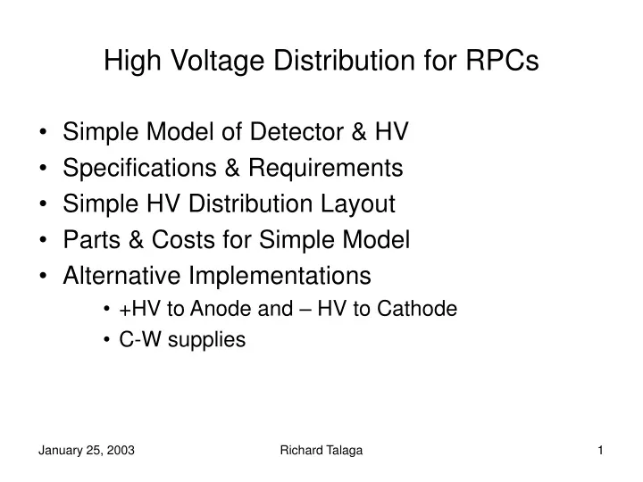
High Voltage Distribution for RPCs. Simple Model of Detector & HV Specifications & Requirements Simple HV Distribution Layout Parts & Costs for Simple Model Alternative Implementations +HV to Anode and – HV to Cathode C-W supplies. Simple Model of Detector & HV. Detector

E N D
High Voltage Distribution for RPCs • Simple Model of Detector & HV • Specifications & Requirements • Simple HV Distribution Layout • Parts & Costs for Simple Model • Alternative Implementations • +HV to Anode and – HV to Cathode • C-W supplies Richard Talaga
Simple Model of Detector & HV • Detector • 300 repetitive layers • 20m x 20m cross section • 2m x 2m per RPC • 100 RPCs per layer • HV • Operating Voltage: ~ 8 kV for ~2mm gap • 1µA/m2 dark current (BELLE result) • mostly through noryl spacers • up to ~ 5µA/m2 if there are problems …(HV drop limits the current) • 400 µA per layer with properly-operating RPCs • Typical commercial HV channel provides ~1mA @10kV • HV System: 1ch/layer 300 channels for entire detector • 1HV channel/100 RPCs; 1 current measurement for an “entire layer” Richard Talaga
Specifications & Requirements • HV distribution: 1 HV channel “per layer” • Ability to turn on/off • Any one RPC? No daisy chains “Simple Layout” • Any of one cluster of RPCs ? Limited daisy chains • Ability to provide more than 1 value of HV per plane • Could accommodate two different HV/plane. “Less Simple” • Ability to track down bad RPC (high current) • Current meters per RPC or cluster of RPCs could be a big help. “Less Simple” Richard Talaga
Simple HV Distribution Layout • 100 RPC/layer • Here each HV channel serves 2 “1/2 layers” • Assume 100 RPC connections to the outside • Four HV distribution boxes per layer (25 ch/box) • 100 pairs of HV connectors/layer + 8 pairs for boxes • 240m of cables per quadrant 960 m/layer Distribution box HV Channel Detector cross section Richard Talaga
Parts and Costs: Simple Model • HV System: CAEN SY1527 (replaces SY 127) $332k • Module A1526: 6 HV ch @ 1mA/15kV per ch • 50 modules 300 channels (1 per layer) $250k • Crate SY1527: fits 8 Modules A1526 • 7 crates (6 full & 1 with two modules) $82k • RG58 cable • 960m/layer x 300 layers =288,000m = 950,000 ft • $136/1000ft spool $129k • SHV connectors: one pair per RPC • RPC end is soldered • 30,000 RPCs x $23/pair (for qty of 100) $690k • Distribution boxes • 1200 boxes @ ~$100/box (no fanout connectors) $120k • 10 kV connectors to PS • 300 x $35 $10k • Total HV M&S costs $1.3M Richard Talaga
Parts and Costs: Notes • CAEN HV modules • 10 kV are being discontinued: SY 127 model A328 • 2mA @10kV ($1,400/channel) • 15 kV model A1526 may be built to provide 10 kV with increased current ~1.3 mA and less potent HV connectors • Note: $830/channel for standard model • Connector cost • 10kV connectors cost $70/pair $36 for bulkhead; $34 for cable • 8kV SHV connectors cost $23/pair $9 for bulkhead; $14 cable • SHV connector cost may be less because quote for qty 100 • Attaching SHV connectors to cables • Assumed no cost in the estimate Richard Talaga
“Less Simple”: Choice of 2 Values of HV per Layer Repeated pattern of higher/lower HV distribution boxes (On left and right sides of detector) HV Channel (low) Layers 1-4 HV Channel (high) Layers 1-4 Richard Talaga
Alternative: +HV to anode and – HV to cathode • Advantages (as in the BELLE experiment) • “Reduces the potential to ground on connectors, cables and surfaces as a precaution against external discharges through and around insulators” • “Helps reduce the overall HV system cost since modules capable of producing voltages in excess of 7.5 kV are less common and therefore more costly” • Available CAEN SY1527 hardware • CAEN A1732(N/P) 6kV @1mA $3,980/12ch $246k system • CAEN A1733(N/P) 4kV @2mA $3,825/12ch $123k system • Compare: A1549 15kV @1mA $5,045/6ch $332k system • Note: Save on HV supplies but double the number of HV connectors, distribution boxes and cables Richard Talaga
Alternative: Cockroft-Walton Supplies * • Each RPC can have its own C-W supply, mounted nearby • One low voltage cable replaces HV cable & connectors • Safer: No HV outside the detector • C-W board: part of RPC “package”; no HV connectors • Can be potted to reduce corona discharge • Can be shielded to reduce rf radiation • Individual RPC HV control possible “Less Simple” • Individual RPC current monitor possible “Less Simple” • Cost compared to $1.3M conventional system • $40/channel seems possible • $40/ch x 30,000 ch = $1.2M • Note: $40/ch is for a “Simple System”; Individual RPC controls/monitors will cost more but are a “natural extension” of the C-W system *Used in ZEUS @2kV Richard Talaga
Block Diagram of +/- 4kV C-W Supply + 4 kV V-mon C-W AMP OSC V-ref ~ Current - 4kV Richard Talaga
Summary • “Simple” HV system will cost ~ $1.3M • labor costs for terminating connectors not included • Largest cost is for HV connectors • Several enhancements to “simple” scheme are probably desirable • RPC current monitoring is important • Positive & Negative Voltage reduces potential to ground • Cockroft-Walton HV system has advantages (adjustable voltage and current monitoring). This could be an interesting R&D project Richard Talaga