Download
1 / 45
450 likes | 581 Views
Modelling. Outline. Modelling methods Editing models – adding detail Polygonal models Representing curves Patched surfaces. Introduction. There are many ways to model objects: none of these are right or wrong Different modelling methods suit different objects and different people

E N D
Outline • Modelling methods • Editing models – adding detail • Polygonal models • Representing curves • Patched surfaces
Introduction • There are many ways to model objects: none of these are right or wrong • Different modelling methods suit different objects and different people • Try some or all of these methods to see which suits you and the type of objects that you want to create
Modelling: types of model • Boundary modelling • Polygonal models • Extrusions and surfaces of revolution • Patches • Procedural modelling • Fractals • Implicit surfaces • Volumetric models • Constructive Solid Geometry (CSG) (which you’ve already seen) • Spatial subdivision
Editing models • Adding detail • Adding/merging/deleting points • Booleans • Transformations • Scales
Polygonal models • As we’ve seen many computer models are made up of polygons, which in turn are made up of points, which are made up of 3 coordinates, x, y and z • Polygons can have any number of sides >= 3 • When we model we should remember certain important points…
Polygons (cont) • When a computer renders our model it needs to know the angle of the surface to the light and the viewer • To do this it needs to calculate the normal to the surface, the vector that represents the direction that the surface is facing • This can be easy or hard depending on the nature of the polygon…
Polygons (cont) • Consider a four-sided polygon: • To calculate the normal, we can take the cross-productof two vectors representing two of the sides • This works because all the points in this example are coplanar: we would get the same normal from any two sides • But what if we raise one vertex?
Polygons (cont) • How do we calculate the normal now thatwe no longer have straight edges? • We can’t since the surface doesn’t point in one direction any more • This can cause major problems for renderers • Solution is to only use triangles, or be certain that your polygons are coplanar
Polygons (cont) • The normal also defines the side of the polygon that is visible: it is invisible from the other side • This is because is has no thickness: i.e. a single polygon could not really exist in the real world • We can cheat and use double sided polygons, i.e. they have a normal pointing out of both sides of them • This is generally bad practice and the mark of poor modelling! • Always think of how the object will be animated when at the modelling stage
Polygons (cont) • Another advantage of triangles is that they must be convex • This makes it easier to render again as the computer can calculate the inside and outside areas of the polygon.
Starting from primitives • Basic building blocks of many complex shapes are the primitives • These can be used to directly construct the shape • They can also be used as a cage for curved surface modelling
Adding detail to primitives • You can use other primitives to add or remove parts of your model (booleans) • You can directly add or remove (or merge) points • You can cut out areas using drills or stencils • You can slice through faces using a knife
Starting from points • Use Create Polygon Tool to draw polygons one by one • Very time consuming but gives ultimate control • Final model is very efficient (i.e. no wasted points)
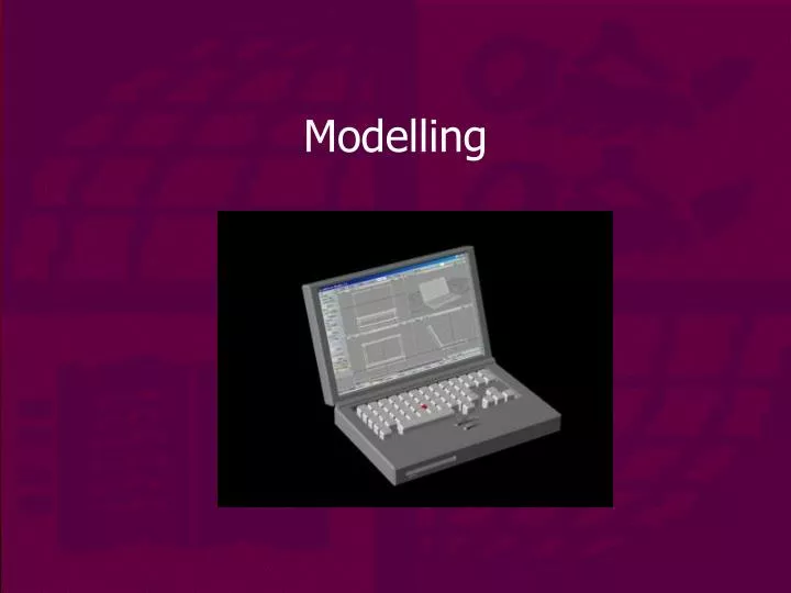
Example: making a laptop • Start from a primitive:
Modify the primitives • Bevel the edges:
Modify the primitives • Boolean subtract
Add some detail • Boolean and bevel
Why use anything else besides polygons? • Need to represent curves: very few objects that we need to model have straight edges • In most modelling programs the final model is approximated with polygons • Curves can be 2D or 3D • There are many ways we can represent curves…
Curve representation • Line segments (polyline) • Simple set of points • Awkward to edit • Large number of points needed • Never truly smooth • Splines • Control points affect regions of curve • Easy to reshape • Truly curved • Compact and efficient to store • Actual curve is a mathematical representation • Usually cubic splines
Splines • Control points can affect curve in different ways • Two main categories • Interpolating spline • Approximating spline
Interpolating splines • Curve passes through control points • Easy to place curve precisely • Difficult to make completely smooth • E.g. Cardinal spline • Passes through all but first and last control point
Interpolating splines • Irregularly placed control points destroys continuity
Approximating splines • Curves passes near control points • E.g. Bézier curves, B-Splines (‘Basis’ Splines) and NURBS (Non-Uniform Rational B-Splines)
Bézier curves • Four control points on minimal curve • Uses tangent vectors to control curvature
Bézier curves (2) • Equation defines the points on the curve:
Bézier curves (3) • Features: • Tangent at each end is equal to straight line connecting the end point to the control point • Moving a control point changes the entire curve to the next control point • Curve does not pass through control points • Convex hull created by connecting the controlpoints contains the curve • Distribution of points along curve is not uniform
Béziercurves (4) • Editing Bézier curves
Bézier curves (5) • Breaking the pair of tangent vectors
B-Splines • Generalisation of Bézier curve • Curve doesn’t extend to first and last control points • Control points only influence local part of curve
NURBS • Non-Uniform Rational B-Splines • Curve passes through first and last control points but not intermediate ones • Has ‘knots’ on the curve which can be moved as well as normal control points • Combines best features of interpolating and approximating splines
Features of curves • All curves have a start and an end. This means we can define points on the curve as t along curve from start. • A parameter defines how far along the curve the point is, so these are called parameterised curves • Can be used to define curved surfaces by moving the curve through space • Moving the spline along a path defined by a second spline creates a patch (or more accurately a bicubic patch if both splines are bicubic curves) • Type of patch depends on type of splines used to create it (e.g. a B-spline patch or Bézier patch) • This creates a network of control points, each of which can be moved individually
Patched surfaces • Patched surfaces are networks of polygons in a regular array • The position of the polygons depends on a number of control points for the defining curves
Summary • Discussed modelling techniques • Looked at a simple example • Introduced curve representations
Cross-product • Given two vectors, A and B, the cross product is defined as:A B = Cwhere C is another vector calculated by:C = ( ya zb – yb za , za xb – zb xa , xa yb – xb ya ) • The length of C is given by:|C| = |A||B|sin( )where is the angle between A and B Back…