Download
1 / 18
180 likes | 356 Views
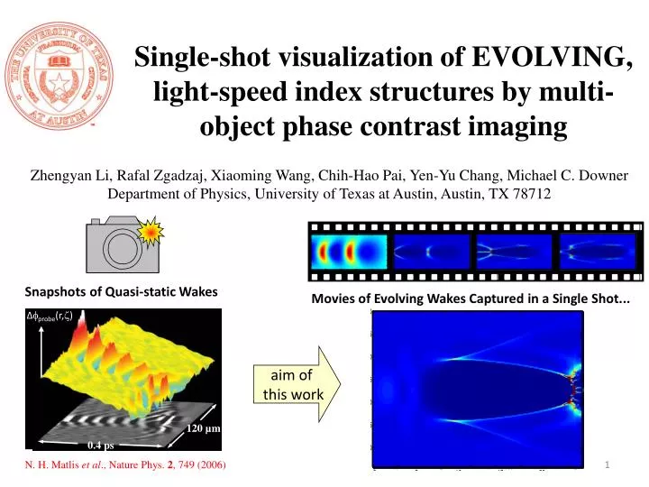
Single-shot visualization of EVOLVING, light-speed index structures by multi-object phase contrast imaging. Zhengyan Li, Rafal Zgadzaj , Xiaoming Wang, Chih-Hao Pai , Yen-Yu Chang, Michael C. Downer Department of Physics, University of Texas at Austin, Austin, TX 78712. ∆ probe (r, ).

E N D
Single-shot visualization of EVOLVING, light-speed index structures by multi-object phase contrast imaging Zhengyan Li, RafalZgadzaj, Xiaoming Wang, Chih-HaoPai, Yen-Yu Chang, Michael C. Downer Department of Physics, University of Texas at Austin, Austin, TX 78712 ∆probe(r,) aim of this work 120 µm 0.4 ps Snapshots of Quasi-static Wakes Movies of Evolving Wakes Captured in a Single Shot... 1 N. H. Matliset al., Nature Phys. 2, 749 (2006)
Evolution of index structures is common in different medium and different applications… Simulation of spatio-temporal splitting of laser pulse in silica Simulation of merging of multi-filament in air Simulation of evolving wakes for e- self-injection in LWFA Evolution of index profile Δn(ξ,x,z) over propagation S. Kalmykov, et al., PRL 103, 135004 (2009) G Mechainet al., PRL 93, 035003 (2004) Simulation of evolving electron driving and witness beam in electron-driven plasma accelerators Ishikawa, et al., PRE 66, 056608 (2002) I. Blumenfeld, et al., Nature 445, 741-744 (2007) Single-shot visualization in laboratory of evolving refractive index structures!
Techniques using transverse probing geometry image spatio-temporal profile Δn(ξ,x,z) of index structures at specific propagation distance, and visualize its z-evolution by shifting the probe-pump delay. Time-resolved polarimetry and plasma shadowgraphy for electron diagnosis A. Buck, et al., Nature Physics 7, 543-548 (2011). • In-line holography for plasma filamentation • D. Abdollahpour et al., Phys. Rev. A 84, 053809 (2011) • G. Rodriguez, et al., J. Opt. Soc. Am. B 25, 1988-1997 (2008) Transverse probing geometry can only visualize z-evolution in multi-shots, and for long interaction length (~101 cm) large aperture beam and optics are not practical.
Holography/tomography in frequency domain visualized spatio-temporal profiles of index structures Δn(ξ,x,z) and its evolution in single-shot, however the interaction length is limited to several mm… • Frequency-domain holography • N. Matlis et al., Nature Physics 2, 749-753 (2006) • J. K. Wahlstrand, et al., Phys. Rev. Lett. 107, 103901 (2011) Frequency-domain tomography Z. Li et al., in preparation
probe θ Multi-object phase contrast imaging with small oblique angle probe maps ~101 cm long z-evolution of index structures’ transverse profiles Δn(ξ,x,z) onto probe’s transverse profile pump 1 mm fused silica plate lens 2 f2 = 75 cm lens 1 f2 = 50 cm CCD 3 CCD n Z. Li, et al., Single-shot visualization of evolving, light-speed structures by multi-object plane phase-contrast imaging, Opt. Lett., in press (2013). CCD 2 CCD 1 The interaction region Object planes: c Phase contrast ccosθ z probe csinθ x • Image planes: • Amplitude • Intensity X y index object z = 0 z = L/2 z = L • To optimally resolve z-evolution • To reduce the object-probe walk-off
To characterize the nonlinear phase shift and absorption in the thin glass plate, close- and open-aperture z-scan measured them respectively… Phase shift at image planes as a function of that at Fourier plane Simply, if ψ0<<1, ψ~ψ0/3
Measured phase shift in different cameras are iteratively reconstructed using Gerchberg-Saxton algorithm, no matter the object at z0 is imaged or not… Diffracted phase shift profiles captured by four CCD cameras Measured intensity modulations Back-projection to z0for phase φi Replace Ai with measured amplitude modulations Average phase shift over φi Forward-projection to z0 for amplitude Ai Reconstructed phase Reconstructed phase shift along z due to the plasma channel 1.7 ps after the pulse
In a single shot, the probe overlapping with the index structure at specific time delay can imaged the transverse profile evolution over propagation… T = 0 fs, pump leading edge T = 66 fs, pump trailing edge • Low plasma density on axis • Pure self-focusing • High plasma density on axis • Self-focusing and plasma de-focusing • Side-peaks developed
If the system is stable that multi-shot operation is possible, 4D visualization with temporal profile characterization of the index structure is possible. Moreover, it is more sensitive to small phase by tenuous laser plasma structures. On-axis index at z = 7.5 cm, y = 0 μm Off-axis index at z = 7.5 cm, y = 100 μm • Plasma channel is formed only on-axis, rather off-axis • Probe with parallel polarization (circle) to the pump has positive rotational index • Probe with perpendicular polarization (square) showed negative rotational index
MOP-PCI: Tilted pulse compensation for large angle probe • Optimal compensation condition • Walk-off angle • Compensation angle • Optimal compensation requires No tilted probe compensation With tilted probe compensation
Visualization of evolving wakefields in laser wakefield accelerators driven by the Texas Petawatt Laser, at extremely low repetition rate L = 10 cm x d = 7 mm pump, e-, x-ray z f# = 40 probe
Primary results of visualizing laser plasma wakefield acceleration structures in the Texas Petawatt Laser Shot 58662 GeVelectrons with 640 TW laser in 6.9e17 cm-3 plasma Shot 58701.5 GeV electrons with 640 TW laser in 6.3e17 cm-3 plasma Shot 5868no electrons with 680 TW laser in 5.5e17 cm-3 plasma • plasma channel is formed, the maximum density is reached at z = 3 to 4 cm, channel width is ~ 1mm and increases with z. • After z = 2.5 to 3 cm, a ``streak’’ is formed in the center of the channel, which is believed to be contribution from plasma wakefields at the 10th to 20th cycles (time delay 2-3 ps). • For shot 5868, plasma channel before z = 2.5 cm is broader than the other two, implying stronger diffraction effect. Further improvement of imaging quality includes better design of gas cell, extended probe beam size, more accurate time delay control…
800 nm, compressed 30 fs(?), < 1 mJ probe pulse, w0 < 1cm The vacuum environment L1 = ? M2 1 deg. angle 35 cm interaction region? M1 OP4 OP1 OP2 OP3 L0 = ? Optical quality window? • What we want to do with index structure n(ζ,x,z)… • Multi-Object-Plane imaging, each object plane (OP) are imaged to different CCD. • Phase shift imprinted on probe at arbitrary z, not limited to OPs, is reconstructed. • In single shot, z-depending transverse profile at specific ζ is obtained. • With multi-shots, full visualization of index object n(ζ,x,z). • Questions: • Is the interaction length 35 cm, or longer? • Where is possible for us to couple laser into the chamber? What are the lengths of L0 and L1? To maintain a good imaging resolution, we hope L1 is not too large, what is the shortest length we can get? • Is there anything that potentially blocks or clips the beam between M1 and M2? Here the angle is 1 deg. = 0.0175 rad, so the inside diameter of the tube containing the laser has to be larger than 3 cm, if L0, L1 ~ 50 cm. Is it OK? Lens f = 75 cm CCD1 CCD2 CCD3 CCD4
Phase shift reconstructed from probe measurement (right) v.s. direct calculation (left) The object is assumed to be a super-gaussian shape blowed-out bubble, the radius is 50 um, plasma density is assumed to be 2e16 cm-3. Maximum phase shift is around 0.4 rad. The trend of transverse profile evolution is reconstructed. Some sharp edge or fine structure information is lost due to a confined simulation box (1.5 cm*1.5 cm), corresponding to hard aperture for actual laser propagation.
For non-evolving bubble, time walk-off or even intentional “opposite compensation” leads to spatio-temporal profile of wakefields c cosθ c sinθ • Optimal compensation condition • Walk-off angle • Compensation angle • Optimal compensation requires z = 0 For stable object, intrinsic pump-probe walk-off + tilted probe “opposite compensation” c Δζ z = L/2 z = L
Specs for MOPPCI in FACET • The minimum angle for oblique angle geometry θmin = λ/πσ = 0.146 deg @ σ = 100 um 0.72 deg @ σ = 20 um • Temporal walk-off Δt = Lθ2/2c = 38 fs @ θ = 0.5 deg 152 fs @ θ = 1 deg • z-resolution for evolving bubble δz = σ/θ = 5.73 mm @ σ = 100 um, θ= 1 deg 11.4 mm @ σ = 100 um, θ = 0.5 deg 2.29 mm @ σ = 20 um, θ = 0.5 deg • ζ-resolution and range for non-evolving bubble δζ = max{σ(θ/2+φ)/c, tpr}= max{50, 30} = 50 fs Δζ = Lθ(θ/2+φ)/c = 1.26 ps @ σ = 100 um, θ = 0.5 deg, φ = 8 deg
Conclusion • Multi-object phase contrast imaging provides evolutional information of the index structure’s transverse profiles over ~101 cm interaction length, by using a small oblique angle geometry. • Nonlinear Kerr effect and absorption improve the sensitivity of detecting small phase shift induced by tenuous laser plasma structure. • In the prototype experiments imaging femtosecond laser filamentation in air, phenomena, like self-focusing, air ionization, plasma induced laser defocusing, and side peaks due to plasma refraction, are observed in a SINGLE SHOT. • If multi-shot is possible, MOPCI at different time delays can be stacked up for a 4D visualization of the index structure. • For laser wakefield acceleration in Texas Petawatt Lasers with 1 pulse/h, single-shot multi-object imaging imaged the 1016 cm-3 plasma channel and wakefields after 10-20 cycles, implying dynamics of laser propagation in plasmas for 2 GeV electron accelerations. This work is supported by DoE grant DE-FG02-07ER54945, DE-FG02-07-96ER40954 and NSF grant PHY-0936283. Thanks! Questions?