Download
1 / 32
340 likes | 575 Views
MAST Thomson Scattering Upgrade Laser Control System: Energy Monitors. João Figueiredo - October 2008. European Doctorate in Fusion Science and Engineering. MAST. First MAST campaign January-June 2000 Plasma cross-section and current comparable to ASDEX-U and DIII-D

E N D
MAST Thomson Scattering Upgrade Laser Control System: Energy Monitors João Figueiredo - October 2008 European Doctorate in Fusion Science and Engineering
MAST • First MAST campaign January-June 2000 • Plasma cross-section and current comparable to ASDEX-U and DIII-D • Adaptable fuelling systems - inboard & outboard gas puffing plus multi-pellet injector • Very good access for diagnostics and camera views
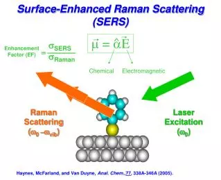
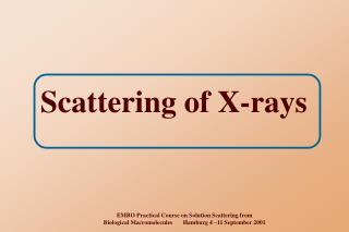
Thomson Scattering Thomson scattering - scattering from free electrons Rayleigh scattering - incoherent scattering from bound electrons in atoms and ions Stray light component - laser radiation scattering from surfaces and windows
MAST Thomson scattering systems Edge Nd:YAG TS system R = 1.25-1.45m,1cm resolution Single pulse 10J ruby laser 4 x 50Hz, 1.2J Nd:YAG lasers Edge TS System Optics Edge System View Laser Beam Path Core System View Core ruby, 300 pts Core Nd:YAG 19 pts Core System Optics
Core TS data • The profiles shown were obtained over the course of a long ELM free H-mode • Edge density builds up over the course of the H-mode and becomes significantly higher than the core density
H-mode - Inter ELM period • Profiles taken during the inter ELM period. Taken with laser separation of ΔT = 5μs. • Camera picture is also taken during the inter-ELM. • No significant variation seen in the Thomson scattering ne and Te profiles. This is typical of the inter-ELM period.
H-mode ELMing • Laser separation: ΔT = 200μs • During the ELM there are large protrusions of the plasma edge from the pre-ELM LCFS (Last Close Flux Surface).
ELM filaments • Laser separation: ΔT = 5μs • As well as protrusions, filamentary structures are seen. • Here 3 sets of filaments ordered by distance from pre-ELM LCFS • It may be seen that the filament temperature falls off rapidly as the filaments move from the plasma edge.
Edge TS data The resolution in the edge region is sufficient to resolve the pedestal gradients.
Pellet Deposition • Pellet deposition profiles have been measured using the Ruby laser system. • Here, three similar pellet injections from three shots are shown. The timing with respect to pellet injection is obtained from interferometer data. (TS system triggered by the pellet). • Profiles approximately constant along flux surfaces.
Reasons for Upgrade • ITB measured in counter injection shot • 3/2 island structure measured in the Ruby profile • Currently these profiles can only be measured once per shot. • We want to measure similar profiles using the Upgraded Nd:YAG system.
Core: • density peaking • sawteeth Inboard & Outboard: • Plasma Rotation from density asymmetry • Constraining EFIT NTMs ITBs Reasons for Upgrade Edge Physics: • gradients • ELM filaments
Project In a joint project with York University, implement improvements to the MAST Nd:YAG Thomson scattering system to give better temporal resolution and improved capability to track fast transient events ESPRC / European Milestone
Project Lasers Spectrometer Room Overview of MAST and relevant areas
Project YAG Laser Room
New Laser Layout Laser 1 Laser 2 Beam Combining Unit
Project Control unit FPGA box (Red) 24 way patch Panel MD 03/04 (Red) 24 way fibre bundle (Cyan) Analogue fibre (Orange) MD 38/39 ADC box MD 05/06 (Yellow) ADC box 2+2 digital fibres (Cyan) Ruby Laser (Red) Optical Receiver Network connection (Green) Pellet route (Purple) Control room MAST Area Digital fibre (Cyan) Compass Area Pellet control / detect (Red) Control System Schematic
Nd:YAG TS upgrade To be fully implemented by 2009. Technical specification • 120 spatial points, ~10mm resolution, 240Hz • Laser energy increased to 1.6J • Number of lasers doubled to 8 (but each laser 30Hz vs 50Hz at present) enhancing burst mode capability for NTM, ELM studies etc. Applications • Transport analysis (spatial resolution comparable to CXRS) including eITB evolution • Transport in and around magnetic islands • Pellet ablation and associated particle transport • Transient events (e.g. ELMs and other filamentary structures)
Energy Monitors System Goals and Requirements • Check in real time proper laser operation • Measure representative fraction of laser power • Implement a robust and flexible system • Future minor operational changes should have none or minor impact in power monitors data output
Design BK7 Uncoated Plano-Convex Lens, D=1.0’’, f=2’’ Unmounted Ø1" Absorptive ND Filter, OD: 1.0 2X SM1ST - SM1 (1.035"-40) to ST Fiber Connector Adapter Plate HeNe Beam Fiber - 62,5/125 µm Parasitic Transmission <1 % YAG Beam 1.6 J Short Wave Pass Dichroic Beamsplitter YAG-HeNe Mirror Polarizer Film IR 3’’ X 3’’ TS Ground Glass Diffuser, D=1.0", 220 GRIT or 1" Round 20º Circle Pattern Diffuser (Engineered)
Specifications Short Wave Pass Dichroic Beamsplitter ■ Reflection > 99.9 % @ 1064 nm ■ Reflected Polarization: S-pol ■ 1’’ diameter ■0.25’’ thick ■ Material: BK7 ■ Incidence Angle: 45º ■ Transmitted Wavelength (nm): 633 ■ Transmitted Polarization: Unpolarised Example for different wavelengths Best solution for low power losses for the YAG beam – reflection better than 99.9%
Specifications Ø1" Absorptive ND Filter, OD: 1.0 2X Worst case scenario without filters ~13mJ after diffuser. Photodiode ~5A ! NE10 ~10% transmission (1064nm). Two filters combined ~ 50 mA. It is assumed flat top profile in the diffuser and 75% power inside 20° solid angle
Specifications Polarizer Film IR 3’’ X 3’’
Specifications BK7 Uncoated Plano-Convex Lens, D=1.0’’, f=2’’ High power loads - coating unnecessary
Ground Glass Diffuser, D=1.0", 220 GRIT DG10-220 – Low Price Best Option (20° ~ 75% of Power)
Specifications Ground Glass Diffuser, D=1.0", 220 GRIT High power loads. Transmission values could be lower with no problem.
Specifications 1" Round 20º Circle Pattern Diffuser (Engineered) Scattered Properties ■ Scatter Shape: Circular ■ Divergence:1 ED1-C20 ED1-C50 20º (Flat Region) 50º (Flat Region) 27º (50%-Max) 54º (50%-Max) 36º (10%-Max) 60º (10%-Max) ■ Incident Beam Size: 0.5mm or Greater !!! ■ Transmission Efficiency: 90% ■ Design Wavelength: Achromatic (400-700nm) Physical Properties ■ Material: Injection Molded ZEONOR ■ Index of Refraction: 1.53 ■ Size: Ø1" (Ø25.4mm) ■ Thickness: 1.5mm ■ Clear Aperture: 95% of Diameter ■ Transmission Spectrum: 380-1100nm ■ Maximum Temperature: 120°C Angles defined for 633nm and collimated illumination. Actual angles may differ from nominal values for other wavelengths or degree of collimation.
Specifications Flat top profile for a wider angle. Price 10x. Will be used if tests rule out ground glass diffusers.
Design SM1ST - SM1 (1.035"-40) to ST Fiber Connector Adapter Plate Fiber - 62,5/125 µm Acceptance Angle 31,924 +/- 1,718º Value calculated from typical numerical aperture for a 62,5/125 µm fiber
Final Design Fibre Polarizer Diffuser Lens ND Filters Laser Beam: Ø10mm 25.4 mm 25 mm 50 mm 75 mm Photodiode OPF482 (1064 nm) – 0.1 A/W ~ 50mA
MAST Thomson Scattering Upgrade Laser Control System: Energy Monitors João Figueiredo - October 2008 European Doctorate in Fusion Science and Engineering