Download

1 / 30
300 likes | 567 Views
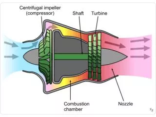
Steam Path Analysis : A Tool To Monitor The Health of A Steam Turbine . P M V Subbarao Associate Professor Mechanical Engineering Department I I T Delhi. A Complete Description of A Device is First Step in Diagnosis. Typical Modern Power Plant Turbine . HP Turbine Rotor. LP Turbine Rotor.

E N D
Steam Path Analysis : A Tool To Monitor The Health of A Steam Turbine P M V Subbarao Associate Professor Mechanical Engineering Department I I T Delhi A Complete Description of A Device is First Step in Diagnosis..
LP LP OFWH 4 CFWH 3 CFWH 2 CFWH 6 CFWH 5 CFWH 1 Block Diagram of A Large Steam Turbine Main Steam Reheat Steam HP IP Steam for Reheating Condenser
Computation of Steam Path • Take the instantaneous measurement of mass flow rate of steam for a given load. • The design of turbine stages and the dimensions of turbine elements in the steam path depend substantially on the volume discharge of steam. • In a typical turbine the specific volume increases 2500 times along the steam path. • In view of the specifics of the steam path computation, all the stages of a steam turbine are divided into four groups. • Governing stage. • Low volume stages (HP Turbine Drum). • Intermediate volume stages (IP Turbine Drum). • Very high volume stages (LP Turbine Drums).
Invariable & Variable Available Infrastructure • Average diameter, d(m) of each stage. • Rotational frequency, n (rps) ,obtained from grid frequency. • Tangential velocity at average diameter U (m/s) calculated using formula u= πdn. • Height of blades in each stage. • Inlet and exit fixed blade angles. • Inlet and exit moving blade angles.
Determination of Instantaneous Velocity Triangles • The turbine in which the steam is delivered to all the revolving blades at the same time, is called Full Admission Turbine. • In a partial admission turbine steam is admitted to only some fraction of the circumference. • Degree of Partial Admission, ε • d : The mean diameter of the disc carrying the blades. • t : Pitch of the blades at the mean diameter. • z : The number of Active blade passages. • The cross-sectional area of the nozzle perpendicular to velocity vector, Vfi.
All the quantities are known in above equations, except Vai& ε . Determine Vai, assuming ε.or Determine ε, assuming Vai. A decrease in velocity or decrease in degree of partial admission will lead to increase in energy losses in nozzle. General Design constraints : ε > 0.2.
U Vri Vai Vai Inlet Velocity Triangle U Vae Vre Vri U Vre Exit Velocity Triangle
U bi ae ai be V’ae V’ri Vai Vae Vri V’re Vre V’ai de di b’i a’e V’ae V’ri V’re V’ai Design Velocity Triangle:
U bi ae ai be Vai Vae Vri Vre b’i a’e V’ae V’ri V’re V’ai Design Velocity Triangle: Off-Design Velocity Triangle:
U Vri Vai Vai Inlet Velocity Triangle U Vae Vre Vri U Vre Exit Velocity Triangle
The inlet relative velocity vector meets the leading edge of moving blades at a negative incidence angle. The steam flow strikes the blade backs, resulting appreciable loss of energy in moving blade passages and respective drop of stage efficiency. The decrease in absolute velocity increases the velocity ratio, f. The increase of velocity ratio also increases the degree of reaction. The relationship may be assumed linear for small variation of velocity.
The behavior of the turbine at part load is determined largely by the way the blading responds toChanges in the steam flow rate. ·The efficiency of the blading is related to the ratio of blade speed to steam speed. Blade speed is constant at different loads because the turbine rotates at a fixed speed. Turbine efficiency therefore depends primarily on Vai.