Download
1 / 27
270 likes | 451 Views
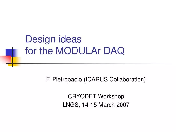
Design ideas for the MODULAr DAQ. F. Pietropaolo (ICARUS Collaboration) CRYODET Workshop LNGS, 14-15 March 2007. Outline. The ICARUS DAQ design Layout for the T600 detector Performance and critical issues Upgraded scheme for MODULAr Same basic architecture

E N D
Design ideas for the MODULAr DAQ F. Pietropaolo (ICARUS Collaboration) CRYODET Workshop LNGS, 14-15 March 2007
Outline • The ICARUS DAQ design • Layout for the T600 detector • Performance and critical issues • Upgraded scheme for MODULAr • Same basic architecture • New components, modularity, cost CryoDet II, LNGS
The ICARUS T600 experience • The T600 DAQ system (5·104 channels), designed in Padova, engineered and built by CAEN, has proven to perform satisfactory during the 2001 test run in Pavia. • It consists of a custom designed analogue front-end followed by a multiplexed AD converter and by a digital VME module performing local storage, hit finding and data compression. • From the experience gained with the T600, we propose a natural evolution, based on the same basic architecture, for a DAQ suitable for multi-kton detectors with >> 105 channels (more performing components, larger integration, lower cost). CryoDet II, LNGS
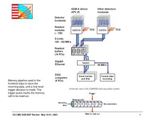
The ICARUS read-out principle m.i.p. ionization ~ 6000 e-/mm Time Edrift ~ 500 V/cm Drift direction Hit finder Mux Memory 8:1 FADC 400ns n x 4kB multi-event circular buffer Low-noise amplifiers Continuous waveform recording To storage Daedalus Front-end CryoDet II, LNGS
The induction signals Ionizing track Induced currentInduced charge Electrons path T=0 Edrift Drift u-t view E1 Induction 1 v-t view d E2 Induction 2 w-t view Charge = ampl. Charge = area d Collection p Drift timeDrift time • ICARUS T600: three wire planes (pitch 3mm, separation 3mm) Edrift = 500 V/cm Mip signal ~ 12000 e- (inc. recombinantion) Electron drift velocity ~ 1.5 mm/s Typical grid transit time ~ 2-3 s CryoDet II, LNGS
Preamplifier for LAr TPC • Need of very low noise amplifier: • No amplification around sense wires • Induced charge ~ 104 electrons • Large input capacitance (CD) • Wires (20 pF/m) + cables (50 pF/m) • In T600 CD ~ 300-400pF • Serial noise (proportional to CD) dominates over parallel noise (proportional only to signal bandwidth) • High trans-conductance (gm) input device is required to ensure acceptable Signal-to-Noise level (S/N ~ 10) CryoDet II, LNGS
Choice of the active input device • Bipolar transistors • gm ≈ 400mS @ Ic ≈ 10 mA (Amplification merit factor gm·Zout ≈ 3-4·105) • BUT: parallel noise density ≈ 2 pA / √Hz too high (with a typical LAr signal bandwidth of ~ 1 MHz gives unacceptable noise contribution) • VLSI-CMOS • Extremely low gm • jFET • Good gm ≈ 40mS @ Ids ≈ 10 mA (Amplif. merit factor gm·Zout ≈ 3-4·104) • negligible parallel noise density ≈ 0.001 pA / √Hz ICARUS choice since 1986: charge sensitive preamplifier with high gm jFET input stage CryoDet II, LNGS
The ICARUS T600 preamplifier Two versions: “quasi-current” mode: RfCf ≈ 1.6s (collection + first induction) “quasi-charge” mode: RfCf ≈ 30s (mid induction) • Custom IC in BiCMOS technology • Classical Radeka integrator • External input stage jFET’s • Two IF4500 (Interfet) or BF861/2/3 (Philips) in parallel to increase gm (50-60 mS) • External feed-back network • Allow sensitivity and decay time optimization • High value f.b. resistor (100M) reduce parallel noise • External baseline restorer circuit • BW noise reduction • Two channels per IC • Identical symmetrical layout guarantees identical electrical behavior Sensitivity ≈ 6 mV/fC Dynamic range > 200 fC Linearity < 0.5% @ full scale Gain uniformity < 3% E.N.C. ≈ (350 + 2.5 x CD) el ≈ 1200 el. @ 350pF Power consumption ≈ 40 mW CryoDet II, LNGS
Layout of front-end electronics H.V. (<±500 V) UHV Feed-through (18x32ch.) VME board (18/crate) Liquid argon Gas Sense wires (4-9m, 20pF/m) 4 Multiplexers (400ns x 8ch.) Twisted pair cables (~5m, 50pF/m) 10bit FADC 50ns sampling 1mV/ADC (~1000e-/ADC matches el. Noise) Front-end amplifiers (32/board) Decoupling Boards (32 ch.) ICARUS T600: ~ 54000 channels — 1720 boards — 96 crates Cost of the full electronic chain: ~ 120 € / channel CryoDet II, LNGS
The ICARUS T600 read-out chain CAEN-V789 board: 2 Daedalus VLSI * 16 input channels (local self-trigger & zero suppression) + memory buffers + data out on VME bus Signal UHV feed-through: 576 channels (18 connectors x 32) + HV wire biasing Decoupling board: HV distribution and signal input CAEN-V791 board: 32 pre-amplifiers + 4 multiplexers (8:1) + 4 FADC’s (10 bits - 20 MHz) CryoDet II, LNGS
The T600 electronic racks CryoDet II, LNGS
The analogue board V791 FADC’s Multiplexers Digital link Preamplifiers BiCMOS IC layout Input signal connector Output of analogue sum Shielding of front-end CryoDet II, LNGS
Analogue board block diagram 32 channel module CryoDet II, LNGS
Signals from the LAr-TPC m.i.p. ≈ 12 ADC counts (3 mm) FWHM ≈ 5 µs Image of a low energy electromagnetic shower Wire numbering (2.54mm pitch). Drift time (400ns sampling). Noise ≈ 1.3 - 1.7 ADC counts rms CryoDet II, LNGS
The digital board (ARIANNA) • Receives 32 channels data stream through the serial link • Hosts two custom made feature extraction ASIC chips (DAEDALUS) for hit finding, zero skipping and self triggering • Complies with VME standards • Each DAEDALUS operates on 16 channel data stream and controls the circular memory multi-buffers. It includes a median filter to reduce high freq. noise • A 28 bit absolute time register is associated to each buffer in memory to allow alignment of data in event reconstruction CryoDet II, LNGS
V791 V789 BOARD BOARD EVENT FIFO EXT. TRIGGERS DAEDALUS LINK CKSYNC CHIPS 2 • 16 ch MUX 8 ANALOG 8:1 CHANNELS CLK 20 MHz On-line data reduction DAEDALUS chip Raw data (one T600 event = 200 Mb) ADC RAM VME INTERFACE 32Current/Charge Preamplifiers Reduced data Daedalus feature: Varying rise-time front-edge finder CryoDet II, LNGS
T600 DAQ throughput • The T600 DAQ is based on VME standard for Digital boards • best choice at time of design in term of throughput (~40 Mbyes/s). • For the analogue boards the same 6U Eurocard standard was adopted, with a custom backplane to connect the inputs from wires and distribute common signals (ADC baseline bias, enable signals, test pulses, etc.). • In the T600 DAQ, 18 ARIANNA boards are housed in one VME crate that serves a total of 576 channels. • One crate is connected to an analogue crate with the same modularity which in turn receives the signals from a single T600 flange (18 feed-through connectors, each hosting 32 channels). • Configuration and control of the 18 boards relies on a dedicated VME CPU, which also handles the data transfers from board buffers to the Ethernet event builder network. • Performance of the DAQ system is bounded by the VME slave ARIANNA interface throughput (8-10 MB/s equivalent to few Hz full drift collection). CryoDet II, LNGS
Critical issues for scaling up • The T600 DAQ was conceived in 1997: • The front-end dual channel BiCMOS and the DAEDALUS circuits were designed on 1998 • The full 5 104 channels system was built, tested and mounted on the T600 by 2001 • The architecture has proven to be reliable and performing • But: impossible to replicate on larger scale because main basic components are discontinued • The scaling up of the ICARUS DAQ to fit MODULAr requirements is based on: • A detail analysis of the whole system to spot the areas where necessary changes could lead to a more efficient structure • An in-depth revision of the DAQ design in term of new components available on the market, channel number (>>105) and cost (aiming at < 60 €/channel) CryoDet II, LNGS
Signals and noise in MODULAr • In a multi-kton TPC we can foresee wires with a pitch larger than the 3mm used in the T600 • The adoption of 6mm pitch for MODULAr seems reasonable and will permit to use most of the existing molds and tools for wires support. • The capacitance associated to each channel will be determined by the capacitance of the wires, in the order of 20pf/m,in parallel with the capacitance of the cable, in the order 50pF/m. • A realistic value for 10m electrode wires, 6mm pitch, and average 8m of cable is a capacitance of ~600pF (cfr.: 300-400pF in the T600) • It follows that the Signal to Noise Ratio from the MODULAr wire chambers should be very similar to that of the T600. • Hence a completely new design of the analogue front-end would hardly improve the performance being the present design already optimized for large input capacitance. CryoDet II, LNGS
The pre-amplifier • In the ICARUS custom IC we integrated two identical channels. • This choice was due to the use of an external input active devices (jFET), the feedback network and the integrating capacitor. • Limitation to two channels makes possible an identical symmetrical layout with an identical behavior for the two channels. • Following this solution, fully satisfactory in the T600, only the amplifier packaging has been reviewed. • This component is already available and more than 105 dies on sealed silicon wafers are also available. • This new smaller package allows a higher degree of integration. • First measurements, made on available prototypes, show performance similar to that of the T600 packaging. Prototype of a four channel amplifier and BW filter based on the new package IC. New package Original used in T600 CryoDet II, LNGS
AD conversion • Serial ADC are preferable over Flash ADC. • They provide the converted data as a sequence of bits at high rate. The data rate of the serial bits is typically around 10-12 times higher than sampling frequency. For instance to reach the 3MHz sampling rate, AD7273 must be clocked at 48MHz. • These devices are quite interesting for price, power consumption and dimensions. Typically they are packed in Mini Small Outline Package (MSOP) smaller than 5x5 mm2. • The choice is rather large and we can expect that more products will be available within one year. • The acceptable sampling frequency for a TPC with 6 mm pitch can be assumed in the range of 1–2Mhz for which there is already a wide choice of devices. • We can assume a resolution of 10bit but 12bit ADCs are also available at reasonable cost. CryoDet II, LNGS
Available Serial ADC The frequency given in the table refers to the sampling rate. CryoDet II, LNGS
New front-end layout • The whole front-end can be hosted in a compact crate very close to the feed-through flange. • A solution is under study with the feed-through flange as a backplane supporting the analogues boards that host amplifiers for 576 channels. • The number of connectors and cables would be drastically reduced with a benefit for cost and S/N. • The new DAQ modularity is defined by the channels served by one flange (576). • This new module, replacing the old analogue board (modulo 32), will also perform digitization before streaming data to the digital buffering board. CryoDet II, LNGS
The new data distribution • A set of a few FPGA for 576 channels will be used to handle, filter, and organize the serial information provided by the serial ADC’s. • Assuming a sampling frequency of 1.5Mhz, 10bit ADC’s and data compression in one byte, we need to transmit ~8 Gbit/s, (including error correction redundancy). • Optical links with 1.5Gbit/s data rates are standards and can be driven by the Rocket-IO™ interfaces available on many FPGA from different vendors. • Six optical links could serve all the channels of one module (576) and convey also extra information as absolute time. • Some of the links will be bidirectional to distribute absolute clock and simple commands. • The ADCs and FPGA’s will be housed in the same crate next to the flange or on special boards on top of the amplifiers boards. CryoDet II, LNGS
Amps and AD module 576 channel module CryoDet II, LNGS
Digital I/O • What has not been discussed is the implementation of the equivalent of the ARIANNA board. • One could say that, nowadays, ASIC VLSI will not be required for hit finding as all the feature extraction and TRIGGERING algorithms can be implemented in powerful FPGA • The architecture of the DAQ system can be enhanced through the adoption of a modern switched I/O, as PCI Express, allowing the parallelization of the data flows. • Such I/O transaction can be carried over low cost optical gigabit/s serial links. • This allows a more effective modularity of the digital hardware architecture, decoupled from the geographical distribution of the signal feed-throughs, thus lending to a larger integration and the consequent lower cost per channel. CryoDet II, LNGS
Summary • The ICARUS DAQ basic architecture is well suited even for larger size LAr-TPC • An in-depth revision of the project based on new modern components and aiming at lower cost (less than 60 € / channel) is underway • Main upgrades concern: • Higher integration of the front-end amplifier • Adoption of high frequency serial ADC • Use of powerful FPGA for data filtering and distribution • Optical link for Gbit/s transmission rate CryoDet II, LNGS