Download
1 / 43
460 likes | 475 Views
Escalator Installation. UT Austin – Robert B. Rowling Hall For EMR and DPR Review (Engineering Review Required) By: CR Watson – Tom Deer Able Machinery Movers Houston. Escalator Installation. UT Austin – Robert B. Rowling Hall For EMR and DPR Review (Engineering Review Required)

E N D
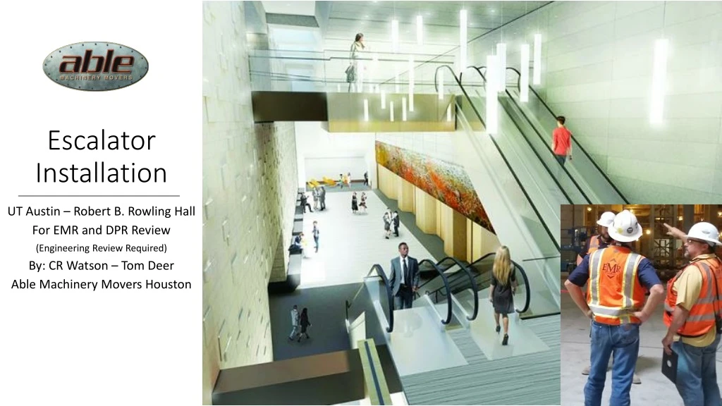
Escalator Installation UT Austin – Robert B. Rowling Hall For EMR and DPR Review (Engineering Review Required) By: CR Watson – Tom Deer Able Machinery Movers Houston
Escalator Installation UT Austin – Robert B. Rowling Hall For EMR and DPR Review (Engineering Review Required) By: CR Watson – Tom Deer Able Machinery Movers Houston
First Step – Six rails at 8ft each need to be built and installed with an expanding bolt system. (See slide for bolt specs) A 5/16 plate is welded to one end and the other is drilled to accept 4” angle iron stops bolted with 3/8” bolts. The stops are installed after the trolley is placed onto the rail. These rails might not be accessible after the escalators are installed.
Safety First Escalator Installation The equipment depicted in these scenes is not necessarily the hardware that will be used. The images are to indicate a function or intention of the rigging task. The Rigging Supervisor, On-Site Safety Coordinator, and the availability of specific equipment will determine what is actually used in the final job. Safety Last
First Step – Six rails at 8ft each need to be built and installed with an expanding bolt system. (See slide for bolt specs) A 5/16 plate is welded to one end and the other is drilled to accept 4” angle iron stops bolted with 3/8” bolts. The stops are installed after the trolley is placed onto the rail. These rails might not be accessible after the escalators are installed.
Installation Strength Rails are installed onto the ceiling using ¾” wedge bolts. The centers of the rails are the center of the ends of the escalators. This will allow approximately three feet in each direction for maneuvering the escalators into alignment and then onto their respective ledges. Trolley Stops: Installed after trolley is put on.
Rails – Each rail supports a trolley and air winch capable of handling 15,500 lbs. The estimated weights per rail when working: 392 – Rail 420 - Trolley/Winch/10ft Chain 153 – 30ft Chain 965 – Subtotal + 15,500 Escalator (Heaviest) = Total of 16,465lbs Average weight per rail when hoisting is 8,233lbs Tension Per bolt in 4000 psi concrete is 16,201lbs. 12 bolts per beam This concrete is 6000psi.
REACHING THE WORK AREA In order to install the beams we need two workers to handle the beam and bolts. This will require an articulating boom man-lift. The GenieZ-40/23N RJ is shown extrapolated into the maximum reach. In the remaining images we show the beams installed with the tab stops toward the escalators, however, it was later determined they will be installed with the tab stops away from the escalators so the hoists can be installed from the open side.
INSTALLING THE HOIST The hoist and trolley combo with 10ft of chain will weigh approximately 420lbs. The chain will weigh an additional 155lbs for a total of 575lbs. This will require a spider crane to lift the hoist, trolley, and chain combination. The riggers will guide the hoist onto the beam and then attach the stops.
INSTALLING THE HOIST The hoist and trolley combo with 10ft of chain will weigh approximately 420lbs. The chain will weigh an additional 155lbs for a total of 575lbs. This will require a spider crane to lift the hoist, trolley, and chain combination. The riggers will guide the hoist onto the beam and then attach the stops.
Assembling The Two Ends The A-Frame hoisting system will be used to hoist and manipulate one half while the other half rests on blocks.
Assembling The Two Ends Once the two halves are joined EMR will finish connecting. Remember that workers will not be able to access the sides where two escalators are next to each other. Therefore belts or wiring that passes through these sides will need to be done before they are hoisted.
Assembling The Two Ends Once the two halves are joined EMR will finish connecting. Remember that workers will not be able to access the sides where two escalators are next to each other. Therefore belts or wiring that passes through these sides will need to be done before they are hoisted.
Assembling The Two Ends As each is finished they can be lowered onto casters to be moved and staged again until ready for installing.
Assembling The Two Ends As each is finished they can be lowered onto casters to be moved until ready for installing.
Assembling The Two Ends As each is finished they can be lowered onto casters to be moved until ready for installing.
INSTALLING THE UNITS Once the two halves are assembled and the escalators readied the 1st escalator is installed into the pit up to the first level. This will be using an overhead rail and the manual gantry on casters. As the escalator is maneuvered around the first level ledge the A Frame will be able to move back and forth. Steel plate on the floor will help with load dispersion.
INSTALLING THE UNITS 1st Escalator is installed into the pit. This will be using a rail overhead and a manual gantry on casters. Steel plate on the floor will help with load dispersion.
INSTALLING THE UNITS 1st Escalator is installed into the pit. This will be using one rail overhead and a manual gantry on casters. Steel plate on the floor will help with load spread under the gantry.
INSTALLING THE UNITS 2nd Escalator is installed into the pit in the same manner. In some images the rails are missing. Since the rails might not be removed it is suggested that we build all 6 and leave them as shown.
INSTALLING THE UNITS 2nd Escalator is installed into the pit in the same manner. In some images the rails are missing. Since the rails might not be removed it is suggested that we build all 6 and leave them as shown.
INSTALLING THE UNITS 2nd Escalator is installed into the pit in the same manner. In some images the rails are missing. Since the rails might not be removed it is suggested that we build all 6 and leave them as shown.
INSTALLING THE UNITS The 3rd Escalator will now use both overhead rails. It will take approximately 1 day to move the air hoist and connect up the lines.
INSTALLING THE UNITS The 3rd Escalator will now use both overhead rails. It will take approximately 1 day to move the air hoist and connect up the lines.
INSTALLING THE UNITS The 3rd Escalator will now use both overhead rails. It will take approximately 1 day to move the air hoist and connect up the lines.
INSTALLING THE UNITS Now the 4th Escalator will be installed.
INSTALLING THE UNITS Now the 4th Escalator will be installed.
INSTALLING THE UNITS Now the 4th Escalator will be installed.
INSTALLING THE UNITS Now the 4th Escalator will be installed.
INSTALLING THE UNITS Now the 4th Escalator will be installed.
INSTALLING THE UNITS Now the 4th Escalator will be installed.
INSTALLING THE UNITS Now the 4th Escalator will be installed.
Warnings and Dimension References - General
Warning: The rigging at the top of the highest lift will be close or will actually two-block the air hoist ! Therefore, the combination of lifting rigging will have to adjusted slightly less that the recommended angle.
Each Escalator has to be centered above their respective placement positions and then lowered straight down into position.
The chain will need to reach nearly the full ceiling height.
Trolleys will need to move about 3ft each way to clear the ledges.
Top escalators will need to lap over approximately 38 inches to allow the top end to clear.