Download
1 / 11
120 likes | 260 Views
SWITCH -MODE POWER SUPPLIES AND SYSTEMS. Lecture No 2. Silesian University of Technology Faculty of Automatic Control, Electronics and Computer Sciences Ryszard Siurek Ph.D., El. Eng. Power supply status indications. Optical indication (usually different colour LEDs)

E N D
SWITCH-MODE POWER SUPPLIES AND SYSTEMS Lecture No 2 Silesian University of Technology Faculty of Automatic Control, Electronics and Computer Sciences Ryszard Siurek Ph.D., El. Eng.
Power supply status indications • Optical indication (usually different colour LEDs) - green - normal operation - red - failure (protection circuit activation) - yellow - warning (e.g. mains voltage decay and battery operation) • Contact indication (rely) - contacts closed - normal operation - contacts open - power failure • Power Fail Signal or PF UOUT DU Dt > 1ms DU < 5%Uo t PF Dt „1” „0” t
UOUT DU DU < 5%Uo • Power Good Signal t „1” PG „0” t
Output voltage hold-up time UIN t 95% Uo UOUT Uo tp t tp – hold-up time (up to several ms)
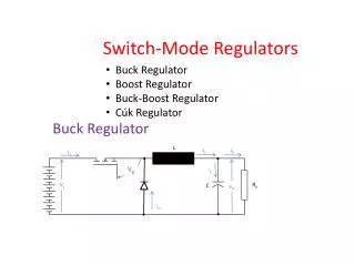
Power Supply protection Overcurrent protection Constatnt current (CC) limiting Power limiting UOUT constant current power limiting switch-off ISC IOUT
3. Output current fold-back UOUT nominal working point resistive load non-linear load possible start-up operating point ISC IOUT 4. Power supply switch-off (fuses 5. Thermal protection
Over-voltage protection FS – feedback loop (voltage regulation) regulated voltage level 2 UOUT UOUTmax FS1 Uo UOUT FS2 switch-off t typical implementation UM - voltage monitoring circuit UM UOUT UOUT switch-off crowbar type overvoltage protection - activates overload or short-circuit protection circuit power supply switching-off
Power leads voltage drop compensation Is = 0 +S Power Supply rs Io DUs Uo U1 Ro Uo rs DUs -S U1 = Uo + 2DUs Feedback circuit controls voltage across +S & -S
Parallel operation of power supplies Increasing of the the total output power I1, I2 Power Supply # 1 I1 U01 I0 Power Supply # 1 100% load I2 U0 I1max Power Supply #2 U02 I1 I2 I0 I1max 2I1max ~ U01 = U02 U01 > U02 I1max = I2max Overload protection circuit with current (power) limitation is required Parallel connection with non-balanced output currents
CS - current share Power Supply # 1 U01 I1 CS I0 I1, I2 additional connection U0 I2 I1max CS U02 Power Supply # 2 I1 I2 I1max = I2max I0 U01 > (<) U02 (may slightly differ) I1max 2I1max Power Supply # 1 (master) forces adequate changes of UO2 to keep I2 close to the actual value of I1 Parallel connection with current share facility (balanced output currents)
Paralleling of power supplies for redundancy (output voltage security) UIN1 D1 I1 Power Supply # 1 U01 I0 I2 I0<I1max, I2max U0 UIN2 U02 Power Supply # 2 D2 ~ U01 = U02 Redundancy 1 + 1 I1max = I2max Redundancy n + x -„n” modules necessary to supply load current - „x” modules which can fail simultaneously