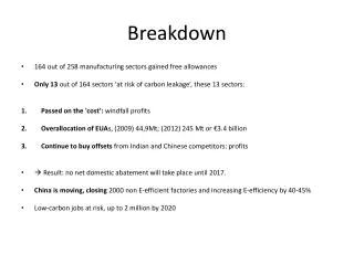
Download
1 / 27
270 likes | 419 Views
A Review on CLIC Breakdown Studies. Helga Timkó , Flyura Djurabekova , Kai Nordlund , Stefan Parviainen , Aarne Pohjonen , Avaz Ruzibaev , Juha Samela , Sergio Calatroni , Rocío Santiago Kern, Jan Kovermann , Walter Wuensch , Helsinki Institute of Physics and CERN

E N D
Helga Timkó A Review on CLIC Breakdown Studies Helga Timkó, FlyuraDjurabekova, Kai Nordlund, Stefan Parviainen, AarnePohjonen, AvazRuzibaev, JuhaSamela, Sergio Calatroni, Rocío Santiago Kern, Jan Kovermann, Walter Wuensch, Helsinki Institute of Physics and CERN In collaboration with the Max-Planck InstitutfürPlasmaphysik
Helga Timkó Outline • Why to model vacuum discharges? • Compact Linear Collider and others • Experiments at CERN • RF and DC breakdowns • Theory: A multiscale model • Tip growth • Plasma formation • Surface damage
Main concern: Vacuum discharges in CLIC • Why to study vacuum discharges? • Going to the limits of conventional acceleration techniques highest possible gradient • Estimated power consumption: 415 MW (LHC: 120 MW) cost reduction by efficiency optimisation • Knowing how to lower breakdown rate is a key issue in points (1) and (2) Detail of a CLIC accelerating structure, working at 100 MV/m
Breakdown studies have a broad application spectrum • Fusion physics • Satellite systems • Industry • Linear collider designs
Issues about breakdown Aim: Predict already in the design phase what breakdown behaviour a structure will have! Why this is not trivial: • Lowering breakdown rate (BDR) • How to prevent breakdowns? = How are they triggered? • Better understanding BDR to predict structure behaviour • Statistical or deterministic, independent events or “memory”? • Influence of material properties, surface treatments? • Interpreting measurements – benchmark against theory; why this is not easy: • Involves many areas of physics • Different phenomena are interacting in a complicated way, involving time scales ~fs – h and length scales ~nm – m • Non-linear evolution of processes
Breakdowns in RF cavities– and how to diagnose them • Breakdown waveform • Normal waveform ― Incident ― Transmitted ― Reflected Transmitted Reflected Incident accelerating structure
Some open questions... • How does BDRw.r.t. gradient scale and why? • What is the physics behind conditioning?
Modelling DC discharges ~ 4-6 kV • First we have to understand breakdowns in DC, before we can generalise to RF • Simple and cost-efficient testing of breakdown behaviour with twoDC setups at CERN • We adjusted also out theoretical model to the DC experimental conditions • How do we know, whether and how results are valid in RF? • Limited energy from the circuit r=1 mm d=20 μm e.g. Cu
Connection between DC and RF? • Connection indicated both by theory and experiments; but how to relate them? Optical spectro-scopy, RF BDR vs gradient in DC and RF: Despite all differences in the experimental setup, slopes are almost the same Optical spectro-scopy, DC Courtesy of J. Kovermann
Conditioning and ranking of materials • Also in DC, materials exhibit conditioning, although differently as in RF. Connection between them? • Ranking of materials according to their breakdown field reached after • Determined by • lattice structure?
An evolving field enhancement? • Does repeated application of the field modify the surface?
Electrical breakdown in multi-scale modeling approach Stage 1: Charge distribution at the surface Method:DFT with external electric field Kai Nordlund, FlyuraDjurabekova ~fewfs AvazRuzibaev Stage 2:Atomic motion & evaporation ; Joule heating (electron dynamics) Method:Hybrid ED&MD model (includes Laplace and heat equation solutions) P L A S M A O N S E T ~fewns FlyuraDjurabekova ~ sec/min ~ sec/hours Stage 3a: Onset of tip growth; Dislocation mechanism Method:MD, analysis of dislocations Stage 3b:Evolution of surface morphology due to the given charge distribution Method:Kinetic Monte Carlo AarnePohjonen Stefan Parviainen Stage 4: Plasma evolution, burning of arc Method:Particle-in-Cell (PIC) ~10s ns Helga Timkó Stage 5: Surface damage due to the intense ion bombardment from plasma Method:Arc MD JuhaSamela ~100s ns Leila Costelle
Stage 1: DFT Method for charge distribution in Cu crystal • Writing the total energy as a functional of the electron density we can obtain the ground state energy by minimizing it. • This information will give us the properties of Cu surface • Total energy, charge states (as defect energy levels) • The calculations are done by SIESTA (Spanish initiative for electronic structure with thousands of atom) • The code allows for including an external electric field • The surface charges under the field are analyzed using the Mulliken and Bader charge analysis
Stage 2: Hybrid ED&MD – Partial surface charge induced by an external electric field • Standard MD solving Newton’s eqs. • Gauss’ law charge of surface atoms • Laplace eq. local field • Motion of surface atoms corrected; pulling effect of the field • Model is submitted for publication in PRE F. Djurabekova, S. Parviainen, A. Pohjonen, K. Nordlund, “Atomistic modelling of metal surfaces under electric fields: direct coupling of electric fields to a molecular dynamics algorithm” Laplace solver Laplace solution φ=const (conductive material) Verification of the charge assessment [DFT] resultsfrom T. Ono et al. Surf.Sci., 577,2005, 42
Short tip on Cu (100) surface at the electric field 10 V nm-1(Temperature 500 K)
↑E0 Je Emax Je Stage 2: Dynamics of electrons for temperature account • At such high electric fields, field emission is a non-negligible phenomenon • Electrons escaping from the surface with significant current will heat the sharp features on the surface, causing eventually their melting. • The change of temperature (kinetic energy) due to Joule heating and heat conduction is calculated by the 1D heat equation Results are submitted to Comput. Mater. Sci., S. Parviainen, F. Djurabekova, H. Timko, and K. Nordlund, “Implementation of electronic processes into MD simulations of nanoscale metal tips under electric fields “
+ + + + + + + + Stage 3a: Onset of tip growth • Presence of an electric field exerts a tensile stress on the surface • Presence of a near-to-surface void may trigger the growth of a protrusion → Fel Force STRESS =0E2/Y Fixedatoms Submitted to PRB: Rapid Commun., A. S. Pohjonen, F. Djurabekova, A. Kuronen, and K. Nordlund, “Dislocation nucleation from near surface void under static tensile stress in Cu”
Corresponding to experiment... Stage 4: Plasmaevolution • 1d3v electrostatic PIC-MCC code; includedphenomena: • Cu evaporation, e- field emission (Fowler-Nordheim eq) • Collisions, esp. ionisation collisions • Sputtering of Cu neutrals at the wall, enhanced MD yield • Secondary electron yield due to ion bombardment Start from these Create ions More e- and Cu Accepted for publication in Contrib. Plasma Phys., H. Timko, K. Matyash, R. Schneider, F. Djurabekova, K. Nordlund, A. Hansen, A. Descoeudres, J. Kovermann, A. Grudiev, W. Wuensch, S. Calatroni, and M. Taborelli , “A One-Dimensional Particle-in-Cell Model of Plasma Build-up in Vacuum Arcs”
Plasma build-up • If not regulated externally, densities grow steadily • Only limiting factor: Energy available • During onset, the plasma does not thermalize, is far from MB distribution (fluid approach not possible)
Under what conditions will an arc form? Two conditions need to be fulfilled:( scaling btw. DC and RF) • High enough initial local field to have growing FE current • Reaching acritical neutral density ionisation avalanche • The sequence of events leading to plasma formation: • ”Point of no return”: lmfp < lsys – corresponding to a critical neutral density ~ 1018 1/cm3 in our case ionisation avalanche High electric field Electron emission, neutral evaporation Ionisation e–, Cu and Cu+ densities build up Sputtering neutrals
Stage 5: Cathode damage due to ion bombardment • Knowing flux & energy distribution of incident ions, erosion and sputtering was simulated with MD • Flux of ~1025 cm-2s-1 on e.g. r=15 nm circle 1 ion/20 fs H. Timko, F. Djurabekova, K. Nordlund, L. Costelle, K. Matyash, R. Schneider, A. Toerklep, G. Arnau-Izquierdo, A. Descoeudres, S. Calatroni, M. Taborelli , and W. Wuensch, “Mechanism of surface modification in the plasma-surface interaction in electrical arcs”, Phys. Rev. B 81, 184109 (2010)
Comparison to experiment • Self-similarity: Crater depth to width ratio remains constant over several orders of magnitude, and is the same for experiment and simulation 10 μm 50 nm
Summary and Outlook • We have established a ranking of materials and understood many bits and pieces of the puzzle already • Still many open questions remain. To answer them, we need a close interaction between theory and experiment • Future of DC experiments: To test more basic physics • Multi-scale model: Give predictions to their outcome New 2D Arc-PIC code
Interested? Come to our Breakdown workshop ‘MeVArc’ June 27-30th, 2011 in Helsinki!Thank you!