Download
1 / 17
170 likes | 230 Views
Project: IEEE P802.15 Working Group for Wireless Personal Area Networks (WPANs) Submission Title: [ Use of the SG3a UWB Channel Model for PHY Proposal Evaluation ] Date Submitted: [ 14 January, 2003 ] Source: [ Matthew Welborn, John McCorkle, Tim Miller ] Company [ XtremeSpectrum, Inc. ]

E N D
Project: IEEE P802.15 Working Group for Wireless Personal Area Networks (WPANs) Submission Title: [Use of the SG3a UWB Channel Model for PHY Proposal Evaluation] Date Submitted: [14 January, 2003] Source: [Matthew Welborn, John McCorkle, Tim Miller] Company [XtremeSpectrum, Inc.] Address [8133 Leesburg Pike, Vienna, VA 22182] Voice:[(703) 269-3000], FAX: [(703) 269-3092], E-Mail:[mwelborn@xtremespectrum.com] Abstract: [Discussion of the SG3a channel model and its use in the evaluation of TG3a PHY proposals.] Purpose: [Provide background information and analysis regarding the SG3a channel model and promote discussion on the subject of PHY proposal multipath performance evaluation.] Notice: This document has been prepared to assist the IEEE P802.15. It is offered as a basis for discussion and is not binding on the contributing individual(s) or organization(s). The material in this document is subject to change in form and content after further study. The contributor(s) reserve(s) the right to add, amend or withdraw material contained herein. Release: The contributor acknowledges and accepts that this contribution becomes the property of IEEE and may be made publicly available by P802.15. Matt Welborn, John McCorkle, Tim Miller, XSI
Outline • Purpose of paper • Address need for a path-loss model • Brief review of SG3a UWB channel model • Using the model to evaluate proposals • Recommendations to facilitate evaluation • Conclusions and Recommendations Matt Welborn, John McCorkle, Tim Miller, XSI
Using the Channel Model to Evaluate PHY Proposals • The goal of developing a UWB channel model was to allow the TG to evaluate PHY proposals • The Selection Criteria document (TG3a 03/031rX) specifically references the channel model for sections which evaluate system performance • Link Budget: proposers provide specific information to show support for required rates and ranges • System Performance: proposers show ability of system to acquire and demodulate in different environments • Recommendations are presented here to facilitate apples-to-apples comparison for PHY proposals Matt Welborn, John McCorkle, Tim Miller, XSI
Issue • Goals of Link Budget (Section 5.6) and System Performance (Section 5.5) • Determine the “link margin” available to a receiver at the specified through-put and ranges • BER, PER and acquisition performance both as a function of received energy (Eb/No) and range for a 90% link success • No common path loss model is provided • Path loss is required to convert “power” to “range” • The 02/490r0 document does not contain recommendations on how to convert “range” to “power” for multipath channels • Inconsistent path loss assumptions will make it difficult to compare PHY proposals Matt Welborn, John McCorkle, Tim Miller, XSI
Review of SG3a UWB Channel Model • Four classes of channels defined • CM1: 0 to 4 meters, Line-of-sight (LOS) • CM2: 0 to 4 meters, Non-LOS (NLOS) • CM3: 4 to 10 meters, NLOS • CM4: Extreme NLOS, 25 ns RMS delay spread • There are 100 pre-computed channel realizations for each of the 4 classes • Power levels of realizations are normalized • Each class of channel realizations is normalized to have an average total power of one (0 dB) • Standard deviation of total power is targeted at 3 dB Matt Welborn, John McCorkle, Tim Miller, XSI
Review of SG3a UWB Channel Model • The SG3a channel model is a statistical impulse train model representing the response of a UWB channel • Impulses are multipath components with amplitudes, arrival times and polarities chosen according to parameterized model • Arrival times are non-uniformly spaced (i.e. “continuous” time) • Equations and detailed description available in 02/490r0 Channel Model Subcommittee Final Report Time Matt Welborn, John McCorkle, Tim Miller, XSI
Review of SG3a UWB Channel Model Component delay of ray in cluster i th channel realization Delay for entire cluster T, : cluster and component arrival times (Exponentially distributed with constants , ) : component amplitudes combine fading of each cluster and ray (log-normal parameters , ), also equiprobable +/- polarity : fading for log-normal shadowing Cluster Matt Welborn, John McCorkle, Tim Miller, XSI
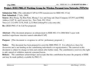
Time System Analysis Using Channel • Convolve transmitted waveform, channel, and receiver antenna/filter Transmitter/Antenna Impulse Response For Example Fc = 8 GHz, RBW = 1 GHz, PRF = 800 MHz Range Normalized Channel Receiver Antenna/Filter Impulse Response Best Detector Sample Point Channel as seen in actual filtered receiver bandwidth Matt Welborn, John McCorkle, Tim Miller, XSI
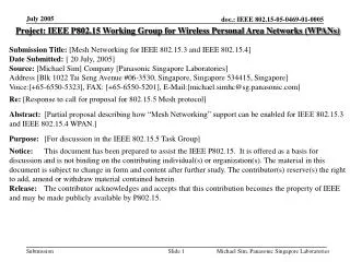
CM2 Distribution of Total Power Difference: Fc = 5 GHz vs. 7 GHz 20 15 # Observations 10 5 0 -6 -4 -2 0 2 4 6 Total Power Difference (dB), 750 MHz BW Review of SG3a UWB Channel Model • Important to apply filtering correctly in system analysis to capture bandwidth and center frequency effects • Bandwidth alone is insufficient to characterize filtered channel: • Power in band varies with center frequency (see figure below) • Peaks vary in both position and amplitude (see plots next page) • If complex-valued constellations are used, we may need to extend model to be complex Matt Welborn, John McCorkle, Tim Miller, XSI
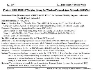
5 Pulse Response UWB Channel Response 0 -5 Magnitude (dB) -10 -15 -20 -25 -30 0 1 2 3 4 5 6 7 8 9 10 Frequency (GHz) -4 x 10 1.5 CM2, Fc = 5 GHz, BW = 0.75 GHz 1 0.5 Matched Filter Output 0 -0.5 -1 -1.5 0 10 20 30 40 50 60 70 80 90 100 Time (ns) -4 x 10 1.5 CM2, Fc = 7 GHz, BW = 0.75 GHz 1 0.5 Matched Filter Output 0 -0.5 -1 -1.5 0 10 20 30 40 50 60 70 80 90 100 Time (ns) Review of SG3a UWB Channel Model Matt Welborn, John McCorkle, Tim Miller, XSI
Recommendations Matt Welborn, John McCorkle, Tim Miller, XSI
Normalizing for Range in LOS Channels • Definition of a LOS channel: • The direct line-of-sight (DLOS) path between TX and RX is not obstructed for RF • Geometry dictates it is the shortest path,but not necessarily the largest signal • The largest amplitude component will be the DLOS path if: • A) The Tx and Rx antennas are roughly aimed at one another along this path, And • B) Other components do not affect DLOS component i.e. The multipath (as measured by the testing waveform) does not decrease the apparent main path signal, And • C) Result of coherent addition of components from multiple angles does not exceed the DLOS signal B DLOS path A Matt Welborn, John McCorkle, Tim Miller, XSI
Evaluation of LOS Assumptions (1) • Regarding A, (Tx and Rx antennas are roughly aimed at one another along DLOS path) • All antennas are directional - So (A) is not necessarily true • Furthermore, how often it is true will depend on the antenna beam pattern and its impulse response consistency over that pattern • Nonetheless, we suggest declaring that we will assume A holds true • For the sake of making relative comparisons with a simplistic model • Regarding B, (Other components do not affect the DLOS component ) • All measurements are of finite bandwidth • So (B) is not necessarily true – multipath can kill the DLOS term • B is true if the channel measurements (and model) are of enough bandwidth to isolate the DLOS path from all other paths. • We suggest declaring that we will assume B holds true in unfiltered SV channel models • For the sake of making relative comparisons with a simplistic model • At least the impulses from the model have infinite bandwidth Matt Welborn, John McCorkle, Tim Miller, XSI
Evaluation of LOS Assumptions (2) • Regarding C, (Coherent addition of components from multiple angles do not exceed the DLOS signal) • All measurements are of finite bandwidth and the geometry is arbitrary • So C is not necessarily true • One could argue theoretically that as the measurement bandwidth goes to infinity the likelihood of an overlap goes to zero, • Measurements show C is often true for very short ranges, because: • the antennas happen to be closer to each other than anything else and • 1/R2 spreading-loss is falling rapidly with range • Measurements show that C is not true at longer ranges • Nonetheless, We suggest declaring that we will assume C holds true in unfiltered SV channel models • For the sake of making relative comparisons with a simplistic model • At least the impulses from the model have infinite bandwidth Matt Welborn, John McCorkle, Tim Miller, XSI
Proposed Range Normalization for LOS Channels • Agree to scale the LOS SV model channels such that the amplitude of the largest component (prior to any bandwidth filtering) will decrease with range as 1/R2 • Assumes that we declare that A, B, and C are true for the SV model outputs • Assumptions hold best if normalization is done prior to filtering to bandwidth and center frequency • Though it may not reflect the real performance or physics, it at least provides a basis for comparison of relative performance Matt Welborn, John McCorkle, Tim Miller, XSI
Path Loss for NLOS Channels • Definition of an NLOS channel: the direct line-of-sight (DLOS) path between TX and RX is blocked for RF • The amplitude of the DLOS (or any other) component is not known • Recommendation: Assume the total received power ensemble average decreases with range as 1/R3 • Roughly consistent with measurements • Provides a basis for consistent comparison B A Matt Welborn, John McCorkle, Tim Miller, XSI
Conclusions and Recommendations • Most important function of channel model is to allow comparison of PHY proposals • This will be easier with consistent path loss assumptions • No changes required to channel model • Normalization can be performed by proposers to produce consistent power levels for any desired analysis “range” • For LOS channels: • Normalize channels such that LARGEST COMPONENT of channel response (prior to filtering) is attenuated as 1/R2 • Each realization in CM1 normalized separately • For NLOS channels: • Normalize channels so that ensemble average for TOTAL POWER of channel responses (prior to filtering) is attenuated as 1/R3 • Realizations in CM2-4 normalized by class to maintain the same log-normal shadowing variations while achieving desired ensemble average Matt Welborn, John McCorkle, Tim Miller, XSI