Download
1 / 11
110 likes | 315 Views
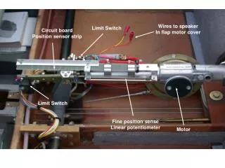
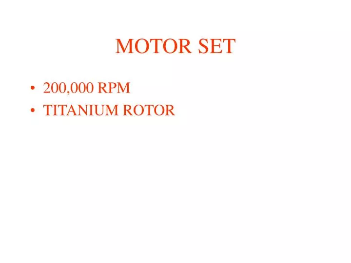
MOTOR SET. 200,000 RPM TITANIUM ROTOR. Finite Element Rotordynamics Model_1 (Schematic) With Ceramic Ball Bearings. This is a schematic of the FE rotordynamics model with 9 elements and 40 degrees of freedom.. The upper half of the model shows the mass distribution

E N D
MOTOR SET • 200,000 RPM • TITANIUM ROTOR
Finite Element Rotordynamics Model_1 (Schematic) With Ceramic Ball Bearings This is a schematic of the FE rotordynamics model with 9 elements and 40 degrees of freedom.. The upper half of the model shows the mass distribution while the lower half shows the stiffness distribution. The mass distribution shows the magnet counted for the mass, but not for the stiffness. The rotor is modeled as one-piece, and hence if the caps are press fit at the ends, this may not be a good way to do it. Welding would be much better. Model 1 shown here has a certain bearing span. You will see that the bending critical speeds are quite sensitive to both bearing stiffness and bearing span. Ball bearing stiffness can vary widely depending on preload, operating internal clearance, etc. In this case the brg stiffness can vary anywhere from 10000 lb/in to 200000 lb/in, resulting in fairly large variations in the 1st critical speed (~155,000 rpm to ~250,000 rpm). Ball bearings have very little damping and hence operating near critical speeds results in very large transmitted forces. You have to absolutely Keep the 1st bending critical speed at least 30% higher than the highest operating speeds.
Critical Speed 1=154933 rpm And Potential Energy Distribution in the Rotor System For the 1st mode (bending mode) strain energy in the shaft represents nearly 94% of the total energy, with 6% of the strain energy due motion at the bearings. However, even this motion at the bearings will transmit large forces. Note that this is only an eigenvalue analysis, not forced response.
Critical Speed 2=514016 rpm And Potential Energy Distribution in the Rotor System For the 2nd mode (bending mode) strain energy in the shaft represents 90% of the total energy, with 10% of the strain energy due motion at the bearings. This is well outside the operating range.
Critical Speed 3=1046720 rpm And Potential Energy Distribution in the Rotor System For the 1st mode (bending mode) strain energy in the shaft represents nearly 98% of the total energy, with 2% of the strain energy due motion at the bearings.
Ball bearing stiffness is estimated to be in the range of 10,000-200,000 lb/in. Note that the first 3 critical speeds can vary a fair amount in this bearing stiffness range. We are only concerned about the 1st critical speed since it is the one near the max operating speed of 200,000 rpm.
Finite Element Rotordynamics Model_2 (Schematic) With Ceramic Ball Bearings Model 2 shown here has a slightly smaller bearing span (by 14 mm) from model 1. Note, however, that this will Result in considerable changes in the critical speed locations. The first mode increases considerably, to around 250k rpm.
Critical Speed 1=245290 rpm And Potential Energy Distribution in the Rotor System For the 1st mode (bending mode) strain energy in the shaft represents about 86% of the total energy, with 14% of the strain energy due motion at the bearings. However, even this motion at the bearings will transmit large forces. Note that this is only an eigenvalue analysis, not forced response.
Critical Speed 2=618425rpm And Potential Energy Distribution in the Rotor System For the 2nd mode (bending mode) strain energy in the shaft represents 83% of the total energy, with 17% of the strain energy due motion at the bearings. This is well outside the operating range. Brg2 has considerable motion at this mode.
Critical Speed 3=872200 rpm And Potential Energy Distribution in the Rotor System Note that this mode could almost pass for a rigid body mode since there is lots of motion at the bearings.
Ball bearing stiffness is estimated to be in the range of 10,000-200,000 lb/in. Note that the first 3 critical speeds can vary a fair amount in this bearing stiffness range. We are only concerned about the 1st critical speed since it is the one near the max operating speed of 200,000 rpm. Bearing stiffness has to be around 100,000 lb/in to get the 1st mode above 200k rpm. THERE ARE STILL DETAILS TO BE RESOLVED FOR THIS BALL BEARING DESIGN. FORCED RESPONSE HAS TO BE SORTED OUT