Download
1 / 38
390 likes | 421 Views
COMUTED TOMOGRAHY. Dr. Amr A. Abd-Elghany. COMPUTED TOMOGRAPHY. It is a non-invasive medical imaging modality that combines the use of X-rays and computer processing to generate tomographic ( ‘ slices ’ ) of the area scanned.

E N D
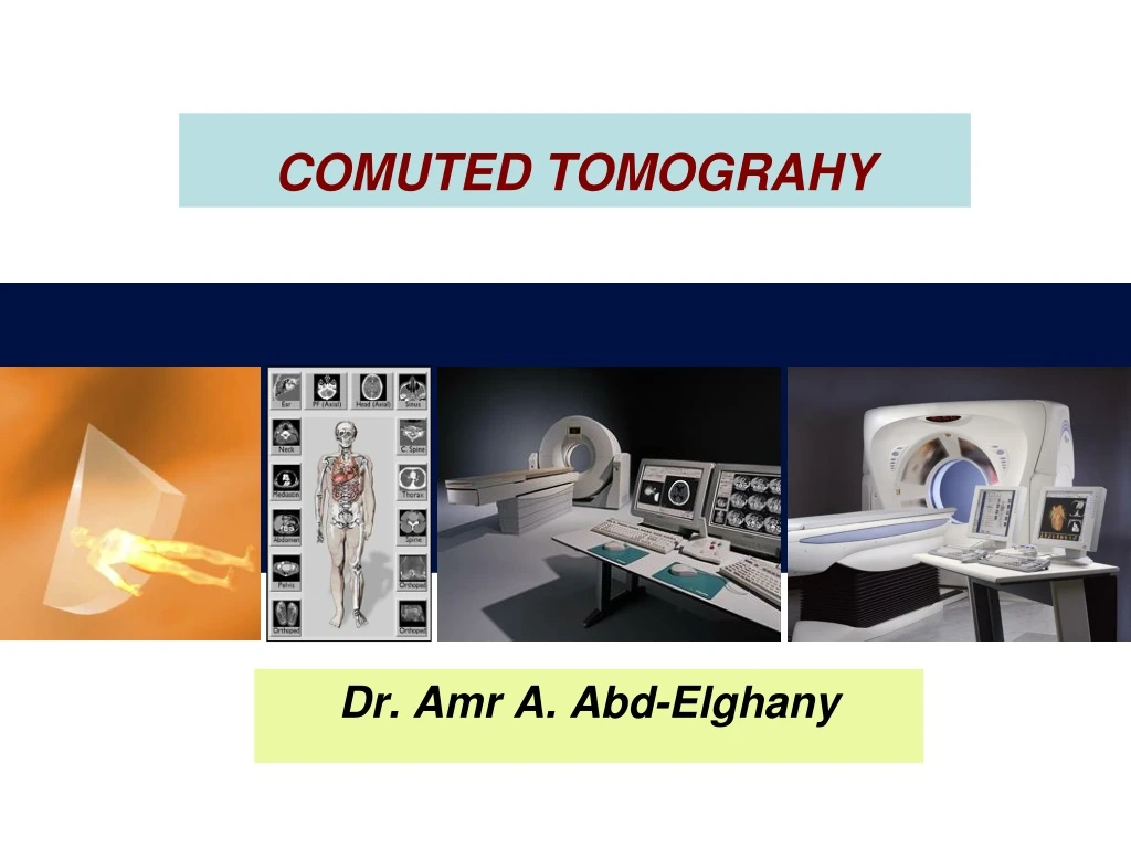
COMUTED TOMOGRAHY Dr. Amr A. Abd-Elghany
COMPUTED TOMOGRAPHY It is a non-invasive medical imaging modality that combines the use of X-rays and computer processing to generate tomographic (‘slices’) of the area scanned. Four classifications of the types of scans: -Abdominal-Bone-Head-Vascular
Tomo = image // to long axis of the bodyCT = image is transverse to the body
X-ray image of the thorax CT scan of the thorax
Why computed tomography? • Mathematical principles of CT were first developed in 1917 by Radon. • Proved that an image of an unknown object could be produced if one had an infinite number of projections through the object. • Plain film imaging reduces the 3D patient anatomy to a 2D projection image. • Used to determine: the extent of Trauma, Location and type of the tumor, status of blood vessels, pre surgical planning.
Why computed tomography? Cont. • Density at a given point on an image represents the x-ray attenuation properties within the patient along a line between the x-ray focal spot and the point on the detector corresponding to the point on the image. • With a conventional radiograph information with respect to the dimension parallel to the x-ray beam is lost. • Large area x-ray beams used in conventional radiography produces considerable scattered radiation that causes blurring images.
CT the beginning • Was formally introduced in 1972 by a British engineer Sir Godfrey Hounsfield • The first scan was done in 1971, of the brain • Physicist Allan Cormack also invented a similar machine in the United States • Both Cormack and Hounsfield were awarded the Nobel Prize in 1979 • First clinical scanners were installed in 1974 • Was a revolutionary invention in terms of medical imaging
PRINCIPLE OF COMPUTED TOMOGRAPHIC IMAGING In early CT imaging devices (“scanners”) a narrow x-ray beam is scanned across a patient in synchrony with a radiation detector on the opposite side of the patient. If the beam is mono-energetic or nearly so, the transmission of x rays I through the patient is I = I0e−μx
Basic CT scanner component • Gantry. • X-ray tube. • Detector. • Control console. Computed Tomography Machine
Gantry • CT X-ray tube. • High voltage generator. • Detector array. • Data acquisition system. • Slip ring: eliminated the need of cables and enables the continuous rotation of the gantry components (electromechanical technology).
Detector Elements • Capture energy that has not been attenuated by the patient
CT Generations1st Generation: Rotate/ translate, pencil beam 1972 • 1 to 3 x-ray detectors used. • Parallel ray geometry. • X-ray tube only able to rotate180 degrees at 1-degree intervals. • About 4.5 min/slice. • Whole chest can be scanned at 1 hr. • Pencil beam allowed very efficient scatter reduction, best of all scanner generations.
Second Generation 1973 • Fan-shaped x-ray beam • 30 or more detectors • 20 seconds per slice or 10 minutes for a 40 slice exam. • 180 degree rotation. • Long data reconstruction time.\.
Third Generation 1974 • Fan-shaped x-ray beam. • 960 detectors opposite the x-ray tube. • Complete 360 degree rotation Rotate/Rotate movement. • One rotation = one slice. • Second data acquisition could be made as the tube and detectors move in the opposite direction. • Time reduced to 1 sec per slice.
Fourth Generation 1975 • Developed in 1980’s. • Fixed ring of as many as 4800 detectors, completely surrounding the patient, Rotate only movement • Rotating x-ray tube provides short bursts of radiation • Detectors collect the remnant radiation to reconstruct into an image • 1 minute for multiple slices
Fifth GenerationStationary/stationary 1984 • Developed specifically for cardiac tomographic imaging. • No conventional x-ray tube; large arc of tungsten encircles patient and lies directly opposite to the detector ring. • Electron beam steered around the patient to strike the annular tungsten target. • Capable of 50msec scan times; can produce fast frame rat CT movies of the beating heart
Modern Scanners • No longer categorize into Generations • Contemporary (modern) CT scanners are either third or fourth generation designs. • Scanners are categorized by tube and detector movement • Slip Ring Technology: connects generator with tube (no cables)
Spiral CT 1986 (Helical CT-volumetric CT)6th generation • Helical (continuous rotation) CT scanners acquire data while the table is moving • By avoiding the time required to translate the patient table, the total scan time required to image the patient can be much shorter • Allows the use of less contrast agent. • In some instances the entire scan be done within a single breath-hold of the patient
Multiple detector array (Multi-slice CT)19997th generation • When using multiple detector arrays, the collimator spacing is wider and more of the x-rays that are produced by the tube are used in producing image data • Opening up the collimator in a single array scanner increases the slice thickness, reducing spatial resolution in the slice thickness dimension • With multiple detector array scanners, slice thickness is determined by detector size, not by the collimator
Procedure • Indications • If physician could not diagnose by plain x-ray. • CT can detect masses, fluids, mediastina and chest wall lesions, pulmonary embolism (blocking of main artery of the lung or one of its branches). • Patient preparation. • Contrast media administration, fasting 4-6 hours. • Patient positioning. • Chest, abdomen, pelvis=AP. • Brain, spine=lateral. • Scanogram
Scanogram cont. • CT will ask you slice thickness 1cm or more or less. • CT will ask you if you will inject contrast or not (lung =no, mediastinum=yes). • Press the button. • The table will be moved 1cm. • Each slice will have 2 images (mediastinal window, lung window) 1 = root of aorta2 = pulmonary outflow3 = left atrium4 = left pulmonary vein5 = superior vena cava6 = descending aorta
Benefit of CT scan • Unlike other imaging methods, fast. • Painless, non-invasive & Accurate • CT Scanning offers detailed views. • Diagnosis made with the assistance of CT can eliminate the need for invasive exploratory surgery & surgical biopsy. • Information to show cross section of body tissue & organ • Use wide range of clinical problems.
Risks of CT scan • CT scan is not generally indicated for pregnant women. • CT scan does involves high radiation exposure • Risk of serious allergic reaction to iodine containing contrast media.
Normal Abdomen CT Oral & IV contrast level of spleen & liver CT angiogram shows pulmonary vessels