Download
1 / 13
180 likes | 534 Views
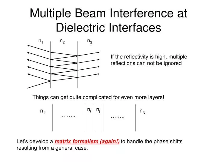
Multiple Beam Interference at Dielectric Interfaces. n 1. n 2. n 3. If the reflectivity is high, multiple reflections can not be ignored. Things can get quite complicated for even more layers!. n i. n j. n 1. n N. ……. …….

E N D
Multiple Beam Interference at Dielectric Interfaces n1 n2 n3 If the reflectivity is high, multiple reflections can not be ignored Things can get quite complicated for even more layers! ni nj n1 nN …….. …….. Let’s develop a matrix formalism (again!) to handle the phase shifts resulting from a general case.
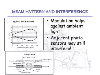
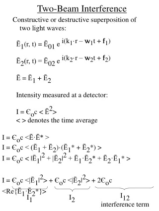
Phase shifts at an interface j i Eri E’ri Erj E’rj …….. …….. Eli E’li Elj E’lj i, j: i-th and j-th layers r, l: fields propagating in the right and left directions Primed, unprimed: right and left side of a given layer Use Stokes relations to simplify
Transition matrices Interface transition matrix Now, let’s determine the phase change upon traversing a layer (we will restrict ourselves to normal incidence) phase change upon moving through a j-th layer with index nj is k*d=nj(2/) dj Layer propagation matrix
Synthesis of it all ni nj n1 nN …….. …….. Notice that the final region (Nth) has no component moving to the left:
Application I:Anti-reflection Coating n1 = 1 n2 = ? n3 = 1.4 /2 /2 air glass d n1 < n2 n2 < n3 Reminder: 180 degree phase shift upon reflection off an interface with a more dense medium. Goal: We want to have a coating of certain thickness so that the destructive interferences between the two rays will give the minimum reflectance for a target wavelength, typically in the middle of visible wavelengths (~550nm). Why do we need n1 < n2 < n3? The reflectivity of two interfaces should match to provide the maximum cancellation between two light fields of comparable strength. Even if these conditions are satisfied, the reflectance for other wavelengths will be non-zero. Let’s evaluate how much better we can do compared to the regular 4% reflection in the absence of the AR coating. -> Use matrix formalism
Anti-reflection Coating n1 n2 n3 /2 /2 air glass d n1 < n2 n2 < n3 Stack matrix for AR coating
Anti-reflection Coating n1 n2 n3 /2 /2 air glass d n1 < n2 n2 < n3 If we require r=0 for =/2 (see above), then ei/2=i, e-i/2=-i. In practice, MgF2 with n2=1.38 is popularly used for its durability. Minimum reflectance is 1%, not 0%.
nH > nL ……. nH nL nH nL nH nL /2 /2 /2 5 /2 5 /2 /2 /2 /2 /2 /2 /2 3 /2 3 /2 /2 /2 /2 /2 /2 /2 /2 Application II: Enhanced Reflection Coating Constructive interferences from multiple layers of coating can give near 100% reflectance! Why is it better to have multiple layers? Let’s find out using matrix formalism.
Enhance Reflection Coating For a pair of two layers (N=1), We can rewrite SN=1 as Then for two pairs of layers (N=2) For N pairs of layers
Enhance Reflection Coating For N pairs of layers Let’s simplify Therefore, R can approach 100% for a very large number of N. A laser cavity mirror with 7 layers of ZnS (nH=2.32) and MgF2 (nL=1.38) giving a peak reflectance of 99.7%.
More is Better n1 = 1 and n2 = 3.556
More is Better n1 = 3.45 and n2 = 3.55