Download
1 / 13
130 likes | 137 Views
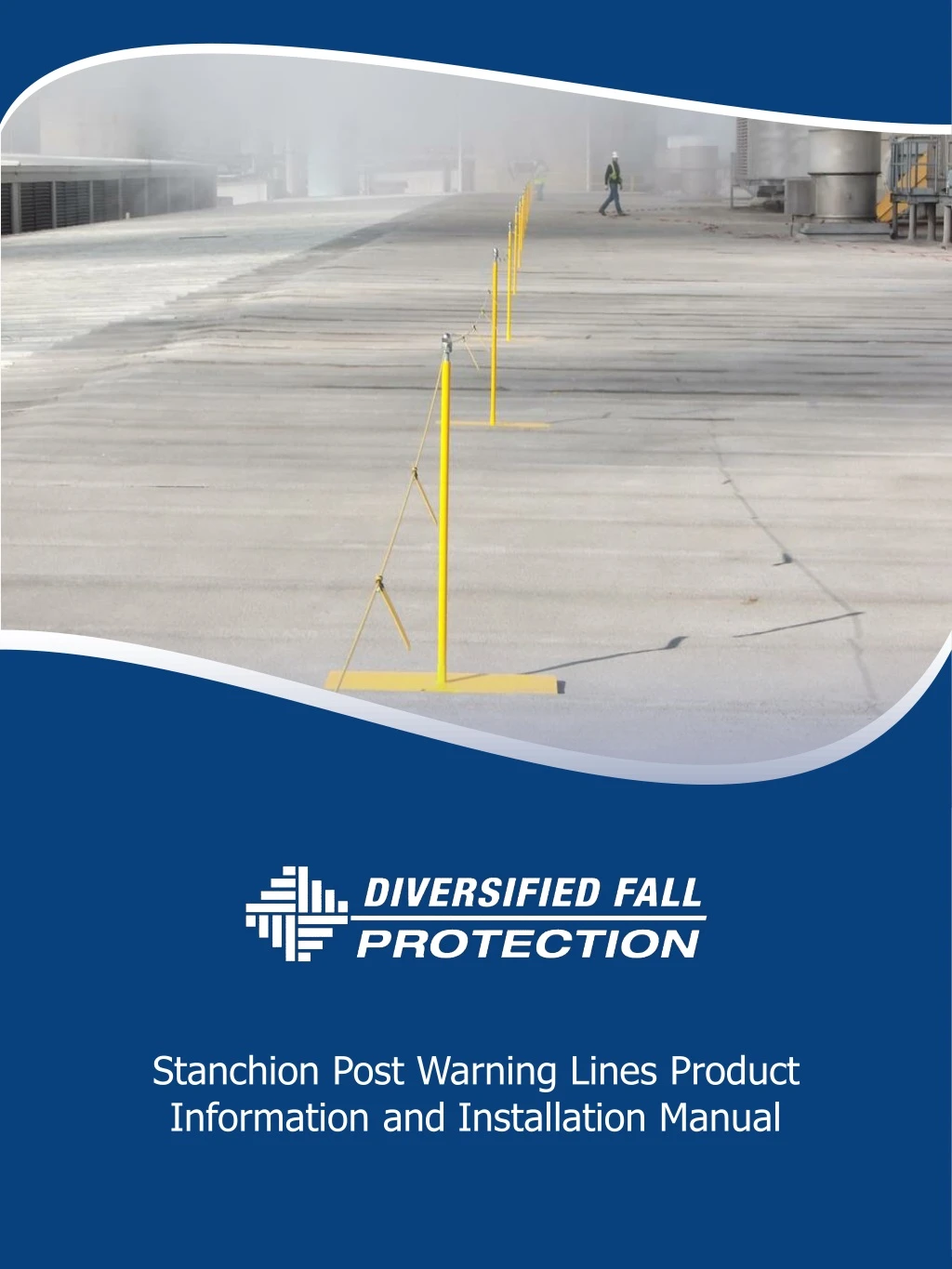
Stanchion Post Warning Lines Product Information and Installation Manual. Where to Use Warning Lines . Per OSHA, when work is infrequent and temporary in nature. How far away from the edge Designated work areas 1910.28(b )( 13) Work on low-slope roofs .

E N D
Stanchion Post Warning Lines Product Information andInstallation Manual
Where to Use Warning Lines • Per OSHA, when work is infrequent and temporary in nature. • How far away from the edge • Designated work areas • 1910.28(b)(13) Work on low-slope roofs. • 1910.28(b)(13)(i) When work is performed less than 6 feet (1.6 m) from the roof edge, the employer must ensure each employee is protected from falling by a guardrail system, safety net system, travel restraint system, or personal fall arrest system. • 1910.28(b)(13)(ii) When work is performed at least 6 feet (1.6 m) but less than 15 feet (4.6 m) from the roof edge, the employer must ensure each employee is protected from falling by using a guardrail system, safety net system, travel restraint system, or personal fall arrest system. The employer may use a designated area when performing work that is both infrequent and temporary.
Typical Applications • Typical Applications: • Roofing Work • HVAC Repair • Inspections INSTALLATION REQUIREMENTS: 1.) POSTS TO BE INSTALLED EVERY 25' 2.) MINIMUM 25' OF CABLE BETWEEN EACH POST 3.) 4 FLAGS PER 25' 4.) 8 ZIP TIES PER 25' 25’ 25’ WL CORNER WL END WL INTER. 25’ WL END
Typical Warning Line Components 1 2 Warning Line Base Plates Yellow Warning Line Cable 3 Warning Line Stanchions
Typical Warning Line Components 4 Yellow Warning Line Flags and Zip Ties 5 Turnbuckles and Corner Connections 6 Crosby Clips
Typical Warning Line Components 4 Thimble 5 End Connections and Corner Connections 6 Plastic PVC Sleeve
Installation Instructions • Layout the Base Plates where the warning line perimeter is to be located - Every 25’ • Thread the stanchion into the receiver welded to the base plate, making sure the hole for the warning line cable is located on top of the stanchion post. This allows the yellow warning line cable to pass through stanchion post
Installation Instructions • Place yellow PVC sleeve over the threaded stanchion post • Thread the 5/8” nut and washer on to the stanchion until they are just below the hole
Installation Instructions • Cut the warning line cable to the length needed to cover one side of the roof perimeter plus an additional one foot • Place thimble inside eye of turnbuckle and terminate cable using one thimble and three Crosby Clips at both ends • Terminate one end of the cable using one thimble and three Crosby Clips at both ends • Run the cable through all the intermediate stanchions and tighten down the acorn nut until it compresses the cable
End Connections Straight Run • Place eye bolt into hole located on top of stanchion post and secure with nylon lock nut • Place eye bolt into hole located on top of stanchion post and secure with nylon lock nut. Attach turnbuckle to eyebolt on both sides of end connections and tighten warning line to desired tension.
End Connections 90 Degrees • Place the two end of the turnbuckle into eyebolt and secure with cotter pin • Place eye bolt into hole located on top of stanchion post and secure with nylon lock nut • Place thimble inside eye of turnbuckle and terminate cable using one thimble and three Crosby Clips at both ends • Terminate one end of the cable using one thimble and three Crosby Clips at both ends • Run the cable through all the intermediate stanchions and tighten down the acorn nut until it compresses the cable
Warning Line Flag Installation • Install flags onto cable (4 flags between each stanchion) • Place yellow zip ties into warning flag and tighten around warning line cable cut off excess zip tie as needed
Contact Info Address : 24400 Sperry Drive. Westlake, Ohio 44145 Phone No : (440) 348-9460 | Toll Free : (800) 504-4016 Email : InfoFallProtect.com | Website: www.FallProtect.com