Download

1 / 9
90 likes | 105 Views
Getting Started: Ansoft HFSS 8.0. Section 3: Projects, HFSS Design Flow. Synopsis. The Project Manager Definitions Directories Project Configuration Management The HFSS Executive Level Executive Window HFSS Design Flow Stages Pre-processing Solution Post Processing.

E N D
Getting Started: Ansoft HFSS 8.0 Section 3: Projects, HFSS Design Flow
Synopsis • The Project Manager • Definitions • Directories • Project Configuration Management • The HFSS Executive Level • Executive Window • HFSS Design Flow Stages • Pre-processing • Solution • Post Processing My E-mail: bfjia@uestc.edu.cn
The Maxwell Project Manager • Analytical modeling efforts using Ansoft software are referred to as “projects” • A “project” consists of files which define a model, files which comprise its solution, and all files which comprise data gathered from that solution • Projects are created, accessed, and managed via the Project Manager button on the main Maxwell toolbar Starting the Maxwell Toolbar: PC: Use shortcut or Run: “maxwell.exe” from install directory UNIX: Type “maxwell &” in Xterm window
The Project Manager Interface Data regarding the currently selected project The Project List: Create, Rename, Copy, Move, and Delete Projects Open the currently selected project The Directory List: Manage Directories and Directory Aliases for Project Storage Recover selected project from any interrupted condition
Project Manager Basics • Project Directories can be existing disk directories on your hard drive, or created as subdirectories to existing directory structure • Do not confuse a “Project Directory”, which contains many projects, with “the project’s directory”, the folder containing all the files for a single project. The latter will have the form “projectname.pjt” • When moving or copying projects, begin in the destination directory • Move and copy permits you to browse to the location of the source; where the command was begun defines the directory the operation will move/copy the project to. • A project’s files are managed so that the setup files must go with any existing mesh and solution data!!! • This is intentional, to preserve the configuration from which any solution was derived. • Editing a project’s setup files may delete meshes and solutions! • To create a variation of an existing solved project, copy the original, and work on the copy! • Recover should unlock projects in the event of access errors • Reclassify allows updating of projects to newer versions of the same software
HFSS Executive Window • This is the starting window seen when opening an HFSS Project. • The checklist at the left accesses project construction steps and reflects current status. • Buttons on the checklist reflect the HFSS project design flow Executive Display Options Executive Display Window Design Flow Checklist Model View Display Options NOTE: All 3D Display windows in HFSS will have a BLACK background. This is not currently editable in HFSS Version 7. Graphical window images have been inverted for this and all subsequent training presentations for better paper reproduction. Solution Monitoring Window
HFSS Design Checklist 1. Define type of project Driven is excitedEigenmode is not 2. Construct the geometry to be analyzed. 5. Set up solution parameters 3. Define materials used in the model. 6. EXECUTE SOLUTION! 7. Review results of analysis Matrix Data and Plot access S-parameters, etc. Fields accesses field visual- ization and calculations 4. Define boundary conditions and source excitations for the model (Optional Step: Define outputparameters for emissionsproblems; access ports-onlysolutions.)
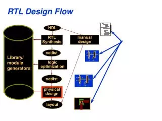
HFSS Analysis Design Flow • Executive Window ‘checklist’ reflects 3 stages of Project design flow • PRE-PROCESSING • All steps necessary to define the problem space and its characteristics • Geometry Construction • Material Assignment (set Volume conditions) • Source/Boundary Assignment (set Surface conditions) • Solution ‘setup’ (desired frequency range, convergence, etc.) • SOLUTION • The actual solution of the problem defined in Pre-Processing above. Most of this step is ‘automatic’ • Excitation Solution • Meshing and Matrix Solution • POST-PROCESSING • Evaluation of the results of the model • Plot S-parameters, other circuit parameters, field quantities, etc. • Generate antenna patterns, RCS response, etc.
HFSS Analysis Design Flowchart Construct Geometry (User Input) 2D Excitation Solution (Automatic) View/Plot S-Parameters (User Input) Define Volume Conditions (User Input) 3D Mesh Generation (Automatic, User Input Optional) Define Surface Conditions (User Input) View/Plot Fields (User Input) Solve 3D Matrix (Automatic) Define Solution Requirements (User Input) PRE-PROCESSING SOLUTION POST-PROCESSING