Download
1 / 2
40 likes | 220 Views
Data Center Cooling Background. Original Production Model. The Problem with Conventional Data Center Cooling.

E N D
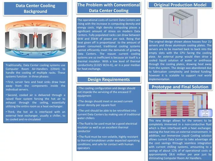
Data Center Cooling Background Original Production Model The Problem with Conventional Data Center Cooling The operational costs of current Data Centers are rising with the increase in computing density and energy costs. High density computing places a significant amount of stress on modern Data Centers. Fully populated racks can draw between 6kW and 35kW of power per rack. Being that heat given off is proportional to the amount of power consumed, traditional cooling systems cannot efficiently meet the demands of growing Data Centers. The reason current cooling systems are so inefficient is because air itself is a thermal insulator. With a low level of thermal conductivity (0.025 W/m-K), air is a poor median for heat exchange. The original design shown above houses four 1U servers and three aluminum cooling plates. The servers are to be inserted back to back into the empty slots with the CPU facing the cooling plate. An external pump would then drive a cooled liquid solution of water or antifreeze through the cooling plates, drawing heat away from the system. The design was abandoned due to fabrication complexity and limited funding, however it is scalable to support real world implementation. • Traditionally, Data Center cooling systems use Computer Room Air-Handlers (CRAH) to handle the cooling of multiple racks. These systems function in three phases: • First, server fans and heat sinks draw heat away from the components inside the individual servers. • Second, cooled air is delivered through a raised floor system forcing the hot air to exhaust through the ceiling, essentially utilizing the entire room as a heat exchanger. • Third, the hot air is interfaced with an external heat exchanger, usually a chiller, to be cooled and re-circulated Design Requirements Prototype and Final Solution • The cooling configuration and design should not impede the servicing of the encased IT equipment • The design should meet or exceed current server density per square foot • The unit should be able to be retrofitted into current Data Centers by making use of traditional water chillers • The fluid to be used must be a good electrical insulator as well as an excellent thermal conductor • The fluid must be non-volatile, highly resistant to thermal breakdown under expected operating conditions, and safe for contact with human operators This new design allows for the servers to be completely immersed in a non-conductive fluid which is then interfaced with a heat exchanger, passing the heat into an external environment. In addition, our Immersive Liquid Cooling solution allows current Data Center to take advantage of the cost savings through seamless integration with current chilling systems, amounting to a savings of about 12% of of operational costs or approximately $8.6 million per year just by eliminating Computer Room Air Handlers. Heat Exchanger & Coolant Reservoir
The ILC Group John Daily Group Leader Major: CPE jdaily@stevens.edu Project Overview Group 17 The scope of this design project is to substitute the heat exchangers within the Computer Room of a Data Center. This will be done by converting conventional rack designs to support complete computer immersion in a non-conductive fluid which is then interfaced with a heat exchanger venting the heat into an external environment. This external environment can include passive or active sources such as a large body of water, geothermal heat pump, or a water-chiller. This design would reduce the number of exchange systems from three (server fans -> Computer Room -> external heat exchanger) to two (Liquid Immersed System -> external heat exchanger). This simplification is expected to reduce the amount of power consumed by the cooling system by up to 12 percent. This coupled with current IT management software and our Monitoring system could yield large savings over traditional Data Centers. Immersive Liquid Cooling William Best Software Major: CPE/CS wbest@stevens.edu Nathaniel Slinin Hardware and Modeling Major: CPE/Tech Mgmt nslinin@stevens.edu Dr. Stuart Tewksbury Faculty Advisor Stevens ECE stuart.tewksbury@stevens.edu For more information, please visit our website: http://www.bridgingclouds.com Heat Exchanger & Coolant Reservoir Senior Design, Spring 2010