Download
1 / 18
220 likes | 565 Views
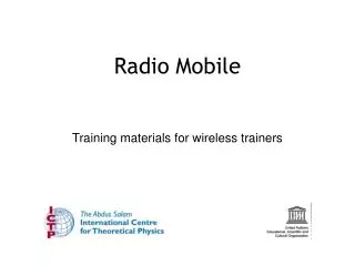
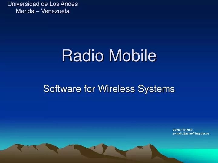
Universidad de Los Andes Merida – Venezuela. Radio Mobile . Software for Wireless Systems. Javier Trivi ñ o e-mail: jjavier@ing.ula.ve. What’s radio mobile?. It is a tool for the design and simulation of wireless systems. Predicts the performance of a radio link.

E N D
Universidad de Los AndesMerida – Venezuela Radio Mobile Software for Wireless Systems Javier Triviño e-mail: jjavier@ing.ula.ve
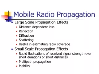
What’s radio mobile? It is a tool for the design and simulation of wireless systems. Predicts the performance of a radio link. You can use digital maps and GIS systems with radio mobile. It is public domain software. Runs in OS Windows 95, 98, ME, NT, 2000 and XP. Uses the terrain elevation for the calculation of coverage, indicating received signal strength at various point along the path.
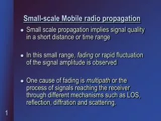
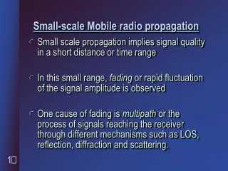
Terrain Profile • Radio Mobile automatically builds a profile between two points in the digital map allowing to see the coverage area and Fresnel ellipsoid for the path. • Digital elevation maps (DEM) are available from several sources. • You can try with different antenna heights to achieve optimum performance.
What does it do? • It works from 20 KHz to 200 GHz. • Calculates the line of sight. • Calculates Path loss, loss in free space. • Create a network of different topologies (net master/slave, PTP and PMP. • Calculate a coverage area of the base station (only for point to multipoint systems).
What do you need to create a Network? • Download Radio Mobile from internet: http://www.cplus.org/rmw/english1.html • Where to get elevation data? • Depend of the method that you use, for example if you decide to use, free world at 30 arc second resolution (~1km), you need to use GTOPO30. http://edcdaac.usgs.gov/gtopo30/gtopo30.html
Gtopo 30 GTOPO30, completed in 1996, was developed over a three year period through a collaborative effort led by staff at the U.S. Geological Survey's EROS Data Center (EDC). The following organizations participated by contributing funding or source data: the National Aeronautics and Space Administration (NASA), the United Nations Environment Programme/Global Resource Information Database (UNEP/GRID), the U.S. Agency for International Development (USAID), the Instituto Nacional de Estadistica Geografica e Informatica (INEGI) of Mexico, the Geographical Survey Institute (GSI) of Japan, Manaaki Whenua Landcare Research of New Zealand, and the Scientific Committee on Antarctic Research (SCAR).
What do you need to create a network? • You get from a GPS the coordinates of your BS and MS or CPE. • Longitude and latitude in Degree, minutes and seconds. Long: XºY’Z’’ W and Lat: XºY’Z’’ N • For example: Site 1 (Main Repeater Galileo 13º43’11’’ E, 45º42’15’’N) • You need to know the specification of your systems: • Topology of the network (Point to multipoint). • Gain of antennas and type. • Max Transmit power (Watt or dBm). • Line Loss or guide wave loss. • Receive power level (dBm). • Antennas height in meters. • Frequency of work. • Polarization Vertical or Horizontal. • Some parameters of radio link and radio communications.
Acquire elevation data Step by step • 1. In View menu, select World map. On the world map picture, click on the desired position for the map center position. • 2. In File menu, select Map properties. This will open a form with all the necessary controls to create a map. Click on Use cursor position button. • 3. Optionally use city or DMS (Latitude and longitude in degree, minute, second) to enter a more precise position for the center of the map. • 4. Select the database and associated logical drive. • 5. Select 400x400 pixels and 100 km size. • 6. Click on the Apply button. • 7. If an error message occurs, verify the database drive and redo from step 2. • 8. In File menu, select New picture (See How to create a map picture).
Radio Coverage • Radio link: • Opens a form with a picture box that shows earth profile, radio performance, and observation features between each pair of units (see Radio link and system performance). • Visual coverage: • Opens a form in order to initiate visual coverage drawing on a map picture (see How to perform visual coverage). • Radio coverage: • Opens a form in order to initiate radio coverage drawing on a map picture (see How to perform radio coverage).
Merida Wireless Networks • We have 3 networks • Two Networks at 11 Mbps. • DSSS installed by University (ULA). (915 MHz and 2.4 GHz). • DSSS installed by FUNDACITE Merida. • One network of State Government installed a Wireless MAN • High speed wireless access 10 Mbps FDX with 21 sector antenna, powered by Spike BroadBand Systems, INC now REMEC. (http://www.remec.com).
Requirements for an installation • GPS (Coordinate of site and elevation). • Binoculars. (Check optical Line of view). • Compass. • Scan of frequency: If you don’t have a Spectrum Analyzer you can use a laptop with a wireless card. • One directive antenna. • Low loss cable (LMR400/LMR600/LMR900).
What we are using? • Orinoco COR 1100. • Antennas: • 24 dBi directional antennas. • 15 dBi omni directional antenna. • Bidirectional Power Amplifier of 1W. • Low loss cable (LMR600/LMR400). • Lighting protectors.
Features of COR • Central Outdoor Router, it has 2 PCMCIA slots for Wireless 802.11b. • It can be connected to a LAN Network with a 10/100 BaseT. • It is an Access Point, Point to Point and Point to Multipoint for an infrastructure mode. • The PCMCIA is connected to an external antenna and external Power Amplifier. • It supports Routing: RIP1 and RIP2, NAT, DHCP.
FUNDACITE Network (Backbone North) City of Merida Timotes Location 60 degree Sector antenna PC router (OS Linux) Switch Router 18.92 Km FUNDACITE LAN (NOC) COR Repeater Mesa Alta 9.15 Km PA 44.15 Km COR El Aguila Repeater PA 34.76 Km PA Switch COR Astronomy Observatory LAN COR Aguada Norte
Next slide 21.7 Km NOC FUNDACITE PA COR El Vigia 40 Km 25.77 Km 360 degree Omni directional antenna 15 dBi PA PA PA PA 40 Km PA PA 40 Km CORs La Trampa Repeaters Tovar Switch FUNDACITE LAN PC router (OS Linux) Backbone South
Casa de Ciencias Tucani 36.08 Km Switch PMP FUNDACITE LAN PC router (OS Linux) PA PA PTP 21.7 Km COR La Uva Repeater PA PMP 10/100 BaseT PA 25.77 Km COR El Vigia Repeater Switch LAN Airport (Business Center) PC router (OS Linux) La Trampa repeater
FUNDACITE LAN (NOC) 9.15 Km PA PA 5.2 Km Canagua COR Aguada Norte LAN Switch/Hub PA PC router (OS Linux) 64.33 Km COR Pico Espejo 3.66 Km PA PA COR Paramo del Motor
ULA – Wireless 2.400 MHz DSSS PC router (OS Linux) PA (500 mW) La Aguada PMP (Ad doc) Peer to Peer Massini(ULA) Rectorado (ULA) LAN LAN PC Gateway (OS Linux) PC Gateway (OS Linux) Arquitectura (ULA) Ingenieria (ULA) PC Gateway (OS Linux) Arquitectura (ULA) PA (500 mW) LAN LAN PC Gateway (OS Linux) LAN PC Gateway (OS Linux)