Download
1 / 21
280 likes | 855 Views
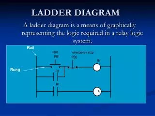
Introduction to IEC1131-3 Ladder Diagram. Origins of Ladder Diagram. CPU. The Ladder Diagram (LD) programming language originated from the graphical representation used to design an electrical control system Control decisions were made using relays

E N D
Origins of Ladder Diagram CPU • The Ladder Diagram (LD) programming language originated from the graphical representation used to design an electrical control system • Control decisions were made using relays • After a while Relays were replaced by logic circuits • Logic gates used to make control decisions • Finally CPUs were added to take over the function of the logic circuits • I/O Devices wired to buffer transistors • Control decisions accomplished through programming • Relay Logic representation (or LD) was developed to make program creation and maintenance easier • Computer based graphical representation of wiring diagrams that was easy to understand • Reduced training and support cost OR AND
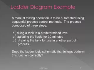
What is a Rung? • A rung of ladder diagram code can contain both input and output instructions • Input instructions perform a comparison or test and set the rung state based on the outcome • Normally left justified on the rung • Output instructions examine the rung state and execute some operation or function • In some cases output instructions can set the rung state • Normally right justified on the rung Input Instruction Output Instruction
Series Vs Parallel Operations • Ladder Diagram input instructions perform logical AND and OR operations in and easy to understand format • If all Input Instructions in series must all be true for outputs to execute (AND) • If any input instruction in parallel is true, the outputs will execute (OR) • Paralleling outputs allows multiple operations to occur based on the same input criteria E A D C B AND F Branches OR IF ((A OR B) AND (NOT C) AND D) THEN E=1; F=1 END_IF
Ladder Logic Execution P S R • Rungs of Ladder diagram are solved from Left to right and top to bottom • Branches within rungs are solved top left to bottom right Ladder Rung A D E Left Power Rail Right Power Rail B Branch F G H I J K
Non Retentive Coils • The referenced bit is reset when processor power is cycled • Coil -( )- • Sets a bit when the rung is true(1) and resets the bit when the rung is false (0) • PLC5 calls this an OTE Output Enable • Negative coil -( / )- • Sets a bit when the rung is false(0) and resets the bit when the rung is True(1) • Not commonly supported because of potential for confusion • Set (Latch) coil -(S)- • Sets a bit (1) when the rung is true and does nothing when the rung is false • Reset (Unlatch) Coil -(R)- • Resets a bit (0) when the rung is true and does nothing when the rung is false
Contacts • Normally Open Contact -| |- • Enables the rung to the right of the instruction if the rung to the left is enabled and underlining bit is set (1) • Normally Closed Contact -|/|- • Enables the rung to the right of the instruction if the rung to the left is enabled and underlining bit is reset (0) • Positive transition contact -|P|- • Enables the right side of the rung for one scan when the rung on left side of the instruction is true • Allen Bradley PLC5 uses -[ONS]- • Negative transition contact -|N|- • Enables the right side of the rung for one scan when the rung on left side of the instruction is false
Retentive Vs Non-retentive Operation • Definitions • Retentive values or instructions maintain their last state during a power cycle • Non-retentive values or instructions are reset to some default state (usually 0) after a power cycle • IEC1131 permits values to be defined as retentive • A contradiction to this is ladder diagram where 3 instructions are classified as retentive • In most PLCs only timer and coil instructions operate as non-retentive
Retentive Coils • The referenced bit is unchanged when processor power is cycled • Retentive coil -(M)- • Sets a bit when the rung is true(1) and resets the bit when the rung is false (0) • Set Retentive (Latch) coil -(SM)- • Sets a bit (1) when the rung is true and does nothing when the rung is false • PLC5 uses OTL Output Latch • Reset Retentive (Unlatch) Coil -(RM)- • Resets a bit (0) when the rung is true and does nothing when the rung is false • PLC5 uses OUT Output Unlatch
Transition Sensing Coils • Positive transition-sensing coil -(P)- • Sets the bit bit (1) when rung to the left of the instruction transitions from off(0) to on(1) • The bit is left in this state • PLC5 use OSR (One Shot Rising) • Negative transition-sensing coil -(N)- • Resets the bit (0) when rung to the left of the instruction transitions from on(1) to off(0) • The bit is left in this state • PLC5 uses OSF (One Shot Falling)
IEC Comparison Instructions in Ladder EQ ENO EN Tank1_Level IN1 100.000 Tank_max IN2 78.251 • If the rung input (EN) is enabled, the instruction performs the operation and sets the rung output (ENO) based on the comparison • Example: when EN is true, EQ (=) function compares In1 and to In2 and sets ENO • Comprehensive instruction set • EQ(=), GT (>), GE (>=), LT (<), LE (<=), NE (<>)
Timers in Ladder Diagram There three timer instructions in IEC1131 TP - Pulse timer TON - Timer On Delay TOF - Timer Off Delay Time values Time base is 1msec (1/1000 of a sec) Values entered using duration literal format Two possible visualizations Depending on use of EN/ENO 1st method requires extra programming if timer done status needs to be referenced on other rungs 2nd method sets a bit with Q which can be referenced by other logic, ENO=EN Pump_Tmr TON IN ENO Pump_Tmr_DN Q T#200ms PT ET 178 Pump_Tmr TON IN Q T#200ms PT ET 178
Timer Operation IN = Rung input condition Q = Comparison output results Varies with timer types PT = Preset Time ET = Elapse Time Pulse (TP) Timing IN Q PT | 0 ET Off-Delay (TOF) Timing IN Q PT | 0 ET On-Delay (TON) Timing IN Q PT | 0 ET
Counters in Ladder Diagram There three counter instructions in IEC1131 CTU - Count Up Counter CTD - Count Down Counter CTUD - Count Up/Down Counter All three count rung transitions Two possible visualizations Depending on use of EN/ENO 1st method requires extra programming if timer done status needs to be referenced on other rungs 2nd method sets a bit with Q which can be referenced by other logic, ENO=EN Load_Cnt CTU IN ENO Load_Cnt_DN R Q 200 PV CV 178 Load_Cnt CTU Q IN R 200 PV CV 178
Counter Operation Parameters CU/CD = Count up/Down Q/QU/QD = Comparison Output R = Reset to Zero LD = Load CV with PV PV = Preset Value CV = Count Value Count Up (CTU) Counter ... ... IN Q PV | 0 CV R Count Down (CTD) Counter ... ... IN Q PV | 0 Count Up/Down (CTUD) Counter CV ... CU LD QU ... CD QD PV | 0 CV R LD
Execution Control Elements Jump / Label Instructions Jump to a label skips a block of code without it being scanned LBL - Named target for a jump operation JMP - Performs a jump when the rung conditions are true CALL / RETURN Instructions Used to encapsulate logic and call it as a subroutine Causes execution to change between functions or subroutines CAL - Passes control to another named function PLC5 uses JSR RET - Exits a function and returns control back to the calling routine | Skip_Calc | |-| |-------------(JMP)--| | ... | | Skip_Calc | |---[LBL]---... CAL CAL RET RET
Different Instruction Presentations Pump_Tmr TON IN ENO Pump_Tmr_DN Q TON (EN) ADD Pump_Tmr Timer Source A Tank1_In T#200ms PT ET 178 (DN) 100.000 Preset 200.000 Source B Offsetr Accum 178.251 78.251 Destination Tank_Level 178.251 + EN ENO Tank1_In Tank_Level 100.000 178.251 Offsetr 78.251 • The look and feel of IEC 1131-3 is somewhat different from the 1Million+ PLC’s that Allen Bradley has running in factories throughout the world • IEC places the input parameters on the outside of the instruction block vs the PLC5 where they are presented inside of the block
Extending the IEC1131-3 Instruction Set • IEC1131-3 Provides a very basic set of instructions to do simple operations (81 Ladder Diagram Instructions) • Data Type Conversion - Trunc, Int_to_Sint, Dint_to_Real, Bcd_To_Int … • Boolean Operations - Bit Test, Bit Set, One Shot, Semaphores … • Timers / Counters - Ton, Tp, Ctu, Ctd, Ctud • Simple Math - Add, Sub, Mul, Div, Mod, Move, Expt • Misc. Math - Abs, Sqrt, Ln, Log, Exp, Sin, Cos, Tan, Asin, Acos, Atan • Bit Shift - Shl, Shr, Ror, Rol • Logic - And, Or, Xor, Not • Selection - Sel, Max, Min, Limit, Mux • Compare - GT, GE, EQ, LE, LT, NE • String - Len, Left, Right, Mid, Concat, Insert, Delete, Replace, Find • Control - JMP, LBL, JSR, RET • All complex operations are left to the user or vendor to define • File Operations, PID, Diagnostic, For/Nxt Loop, Search, Sort are not in IEC1131-3 • Extensions to the instruction set are permitted so that vendors can add instructions that their customers need • All vendors have defined their own set of extensions • Rockwell Automation controllers have significantly more capabilitywith over 130 Ladder Instructions
Extensions to IEC provide codeoptimization and ease of use IEC1131-3 Load FIFO Logic Rockwell Automation FIFO Load Instruction = 1 Rung of Logic 1 Instruction Minutes to code and debug 11 Rungs of Logic 17 Instructions Hours to code and debug
Rockwell AutomationInstruction Extension to IEC1131-3 • FIFO & LIFO - FFL, FFU, LFL, LFU • File math and search - FAL, FSC • Table operations - SRT, STD, AVE • Sequencers - SQI, SQL, SQO, SDS • Diagnostics - DDT, DFA, FBC • Compare - CMP, MEQ • Compute - CPT, NEG • Data moves - MVM, COP, BTD • Program Control - AFI, NOP, MCR, TND • Interrupt Services - UID, UIE • Retentive Timer - RTO • Ladder Loop Instruction - FOR, NXT • Process - PID • Motion - 30+ instructions to perform closed loop servo control