Download
1 / 90
910 likes | 1.12k Views
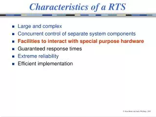
Characteristics of a RTS. Large and complex Concurrent control of separate system components Facilities to interact with special purpose hardware Guaranteed response times Extreme reliability Efficient implementation. Low-level Programming. Review hardware I/O mechanisms

E N D
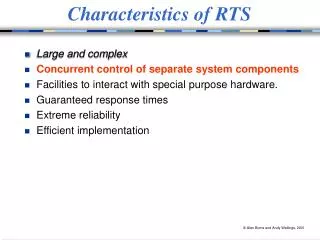
Characteristics of a RTS • Large and complex • Concurrent control of separate system components • Facilities to interact with special purpose hardware • Guaranteed response times • Extreme reliability • Efficient implementation
Low-level Programming • Review hardware I/O mechanisms • Look at language requirements and various models of device driving • Consider the Modula-1, Ada, Real-Time Java and C models of device driving • Memory Management • Aim: • to show how the various models of processes and their communication and synchronisation mechanisms can be extended to allow devices to be modelled and controlled • to consider efficient real-time memory management
Hardware Input/Output Mechanisms • Two general classes of computer architecture: Data Data CPU Memory Devices Devices Address Address Separate Buses for Devices and Memory
Memory Mapped Architecture Data CPU Memory Devices Devices Address
Device Interface • The interface to a device is normally through a set of registers • Separate buses: two sets of assembly instructions — one for memory access the other for device register access • The latter normally take the form of: IN AC, PORT OUT AC, PORT • E.g., the Intel 486 and Pentium range • Memory-mapped I/O: certain addresses access memory others the device registers; e.g., M68000 and PowerPC ranges • The interface is used to control the device’s operations and to control the data transfer • Two control mechanisms: status driven and interrupt driven control
Status Driven • A program performs explicit tests in order to determine the status of a given device • Three kinds of hardware instructions: • test operations that enable the program to determine the status of the given device • control operations that direct the device to perform non-transfer device dependent actions such as positioning read heads • I/O operations that perform the actual transfer of data between the device and the CPU • Nowadays most devices are interrupt driven. Interrupts can of course be turned off and polling of device status used instead. • Interrupts are often no allowed in Safety Critical Systems
Interrupt Driven • Interrupt-driven program-controlled • Interrupt-driven program-initiated (DMA) • Interrupt-driven channel-program controlled DMA and channel programs can cause cycle stealing from the processor; this may make it difficult to estimate the worst-case execution time of a process
Elements Needed for Interrupt Driven Devices 1Context switching mechanisms • Preserving the state (PC, registers, program status info - priority, memory protection etc.) of the processor immediately prior to the occurrence of the interrupt. • Placing the processor in the required state for processing the interrupt. • Restoring the suspended process state after the interrupt processing has been completed. • basic: just the PC is saved; • partial: PC and the PSW are saved; • complete: full context is saved. • It may be necessary to supplement the actions of the hardware by explicit software support
Elements Needed 2Interrupting device identification • A vectored mechanism consists of a set of dedicated, contiguous memory locations (an interrupt vector) and a hardware mapping of device addresses onto the interrupt vector • With a status mechanism, each interrupt has an associated status word which specifies the device causing the interrupt and the reason for the interrupt • The polling device identification mechanism involves interrogating the status of each device • With some modern computer architectures, interrupt handling is directly associated with a high-level language primitive • With these systems, an interrupt is often viewed as a synchronisation message down an associated channel; the device is identified by the channel which becomes active
Elements Needed 3Interrupt identification • Once the device has been identified, the appropriate interrupt handling routine must determine why it generated the interrupt • This can be supplied by either status information provided by the device or by having different interrupts from the same device occurring through different vectored locations or channels
Elements Needed 4Interrupt control • Once a device is switched on its interrupts must be enabled. Enabling/disabling of interrupts may be performed by: • Status mechanisms provide flags to enable/disable interrupts. • Mask interrupt control mechanisms associate device interrupts with particular locations in an interrupt mask word • Level-interrupt control mechanisms have devices associated with certain levels;the current level of the processor determines which devices may or may not interrupt
Elements Needed 5Priority control • Some devices have higher urgency than others and, therefore, a priority facility is often associated with interrupts • This mechanism may be static or dynamic and is usually related to the device interrupt control facility and the priority levels of the processor
A Simple Example I/O System • Loosely based on the Motorola 68000 series of computers; the registers are memory mapped • Control & status registers contain all the information on a device’s status, and allow the device’s interrupts to be enabled / disabled. bits 15 - 12 : Errors 11 : Busy 10 - 8 : Unit select 7 : Done/ready 6 : Interrupt enable 5 - 3 : reserved 2 - 1 : Device function 0 : Device enable
A Simple Example I/O System • Data buffer registers act as buffer registers for temporarily storing data to be transferred into or out of the machine via the device 15 - 8 : Unused 7 - 0 : Data • A device may have more than one csr and dbr, the exact number being dependent on the nature of the device. • On an interrupt, the processor stores the PC and the current program status word (PSW) on the system stack • The new PC and PSW are loaded from an interrupt vector • The first word contains the address of the interrupt service routine and the second contains the PSW including the priority at which the interrupt is to be handled
Language Requirements • Modularity & encapsulation facilities • Device interfacing is machine dependent. It is important to separate the non-portable sections of code from the portable ones. • In Modula-1, devices are encapsulated in special modules. • In Ada, the package is used. • In Java, classes and packages • In C, it is a file • An abstract model of device handling • A device can be viewed as a processor performing a fixed task. A computer system can be modelled as several parallel processes which need to communicate and synchronise; synchronisation is provided by the interrupt
Abstract Models • All models require facilities for addressing and manipulating device registers • A device register may be represented as a program variable, an object, or even a communications channel • A suitable representation of an interrupt: • procedure call • sporadic process invocation • asynchronous notification • shared-memory based condition synchronisation • message-based synchronisation • All except procedure view the handler as executing in the scope of a process, and therefore require a full context switch
Abstract Models • C/C++ use a procedural model with variables as device registers • The Ada model is a hybrid between the procedural model and the shared memory model; protected procedure calls represent interrupts and variables are used for device register • RTJ views an interrupt as an asynchronous event which is scheduled • Modula-1 and RT Euclid used the shared memory model: Modula-1 maps condition variable to interrupts; RT Euclid uses semaphores • Occam2 uses a message-based model
Modula-1 • A Pascal-like language with the addition of processes and modules • A special type of module, called an interface module, has the properties of a monitor and is used to control access to shared resources • Process interact via signals (condition variable) using the operators wait, send and awaited • First language to attempt device driving in a high-level language • A device module is a special type of interface module used to encapsulate the interaction with a device. • It is only from within a device module that the facilities for handling interrupts etc. can be used
Modula-1: Modules MODULE main; TYPE dimension = (xplane, yplane, zplane); PROCESS control (dim : dimension); VAR position : integer; (* absolute position *) setting : integer; (* relative movement *) BEGIN position := 0; (* rest position *) LOOP new_setting (dim, setting); position := position + setting; move_arm (dim, position) END END control; BEGIN control (xplane); control (yplane); control (zplane) END main.
Modula-1: Hoare’s Monitors INTERFACE MODULE resource_control; DEFINE allocate, deallocate; (* export list *) VAR busy : BOOLEAN; free : SIGNAL; PROCEDURE allocate; BEGIN IF busy THEN WAIT(free) END; busy := TRUE; END; PROCEDURE deallocate; BEGIN busy := FALSE; SEND(free) END; BEGIN (* initialisation of module *) busy := FALSE END.
Addressing/Manipulating Device Registers • Associating a variable with a register is expressed by an octal address following the name in a declaration. • E.g. a data buffer register for the simple I/O architecture VAR rdbr[177562B] CHAR; • 177562B is an octal address which is the location of the register in memory • Only scalar data types can be mapped onto a device register; registers which have internal structures are considered to be of the predefined type bits whose definition is: type bits = array 0:no_of_bits_in_word OF BOOLEAN; • Variables of this type are packed into a single word
Addressing/Manipulating Device Registers • A control and status register at octal address 177560 can therefore be defined by: VAR rcsr[177560B] : BITS; • The following will enable the device and turn interrupts off rcsr[0] := TRUE; rcsr[6] :=False; • In general these facilities are not powerful enough to handle all types of register conveniently; consider setting 10 - 8 : Unit select • to the value 5 rcsr[10] := true; rcsr[9] := false; rcsr[8] := true; Clumsy
Note • On many machines more than one device register can be mapped to the same physical address; these registers are often read or write only • Care must be taken when manipulating device registers; If the CSR was a pair of registers mapped to the same location, the code will not have the desired affect WHY? • It is advisable to have other variables in a program which represent device registers; these can be manipulated in the normal way • When the required register format has been constructed it may then be assigned to the actual device register • Such variables are often called shadow device registers
Interrupt Handling in Modula-1 • Based around the concept of an ideal hardware device with the following properties • Each device operation is known to produce either no interrupt or at least one • After an interrupt has occurred the device status indicates whether or not another interrupt will occur • No interrupt arrives unexpectedly • Each device has a unique interrupt location • The facilities provided: • Each device has an associated device module • Each device module has a hardware priority specified in its header following the module name • All code within the module executes at the specified hardware priority
Modula-1 Facilities • Each interrupt to be handled within a device module requires a process called a device process • When the device process is executing it has sole access to the module (i.e. it holds the monitor lock) • A device process is not allowed to call any non-local procedures and cannot send signals to other device processes; this is to ensure that device processes will not be inadvertently blocked • When a device process sends a signal, the receiving process is not resumed but the signalling process continues (this is to ensure that the device process is not blocked) • Wait statements within device processes may only be of rank 1
Modula-1: Interrupts • An interrupt is considered to be a form of signal, the device process, however, instead of issuing a wait request issues a DOIO request • The address of the vector through which the device interrupts is specified in the header of the process • Only device processes can contain DOIO statements • DOIO and wait calls lower the processor priority and therefore release the monitor lock • Only one instance of a device process may be activated
Clock Handler in Modula-1 DEVICE MODULE rtc[6]; (* hardware priority 6 *) DEFINE tick; VAR tick : SIGNAL; PROCESS clock[100B]; (* interrupt vector address *) VAR csr[177546B] : BITS; (*CSR *) BEGIN csr[6] := TRUE; (* enable interrupts *) LOOP DOIO; (* wait for interrupts *) WHILE AWAITED(tick) DO SEND(tick); END END END; BEGIN clock; (* create one instance of the clock process *) END rtc;
Modula-1 and Interrupt-Driven Devices • Device control — I/O registers are represented by variables • Context switching — the interrupt causes an immediate context switch to the handling process, which waits using the DOIO • Interrupt device identification — the address of the interrupt vector is given with the device process’ header • Interrupt identification — in general the device status register should be checked to identify the cause of the interrupt • Interrupt control — the interrupt control is status driven and provided by a flag in the device register • Priority control — the priority of the device is given in the device module header; all code in the module runs at this priority
An Example Terminal Driver DEVICE MODULE Keyboard[4]; DEFINE readch; CONST size=64; (* buffer size *) VAR KBS[177560B]: BITS; (* keyboard status *) KBB[177562B]: CHAR; (* keyboard buffer *) in, out, n : INTEGER; nfull, nempty : SIGNAL; buf : ARRAY 1:n OF CHAR;
PROCEDURE readch(VAR ch : CHAR); BEGIN IF n = 0 THEN WAIT(nempty) END; ch := buf[out]; out := (out MOD size)+1; DEC(n); SEND(nfull) END readch; The buffers must be included in the device module because device processes cannot call non-local procedures
PROCESS keyboarddriver[60B]; BEGIN LOOP IF n1 = n THEN WAIT(nfull) END; KBS[6] := TRUE; DOIO; KBS[6] := FALSE; buf[in] := KBB; in := (in MOD size)+1; INC(n); SEND(nempty) END END keyboarddriver; BEGIN in :=1; out :=1; n :=0; keyboarddriver; END terminal. Example in book, has display handler in same module
Timing Facilites DEVICE MODULE hardwareclock[6]; DEFINE tick; VAR tick : SIGNAL; PROCESS handler[100B]; VAR count : INTEGER; statusreg[177546B] : BITS; BEGIN count := 0; statusreg[6] := TRUE; LOOP DOIO; count := (count+1) MOD 50; IF count = 0 THEN WHILE AWAITED(tick) DO SEND(tick) END END END END handler; BEGIN driver END hardwareclock;
INTERFACE MODULE SystemClock; DEFINE GetTime, SetTime; USE time, initialise, add, tick; VAR TimeOfDay, onesec : time; PROCEDURE SetTime(t: time); BEGIN TimeOfDay := t; END SetTime; PROCEDURE GetTime(VAR t: time); BEGIN t := TimeOfDay END GetTime; PROCESS clock; BEGIN LOOP WAIT(tick); addtime(TimeOfDay, onesec) END END clock; BEGIN inittime(TimeOfDay, 0, 0, 0); inittime(onesec, 0, 0, 1); clock; END SystemClock; The clock process is logically redundant. The device process could increment TimeOfDay directly thereby saving a context switch. However, Modula-1 forbids a device process to call a non-local procedure.
Problems with the Modula-1 Approach • It does not allow a device process to call a non-local procedure; therefore you have to include extra functions into a device module (e.g. bounded buffer in terminal driver), or introduce extra processes to wait for a signal sent by a device process (e.g. clock) • It only allows a single instance of a device process; this makes the sharing of code between similar devices difficult; the problem is compounded by not being able to call non-local procedures • Modula-1 was design for memory mapped machines and consequently it is difficult to use its facilities machines with special instructions VAR x AT PORT 46B : INTEGER; • It is not possible to define variables that are read/write-only in Modula-1
Interrupt Handling and Device Driving in Ada • A device driver is a subsystem which has responsibility for controlling access to some external device; it must manipulate device registers and respond to interrupts • The device can be modeled as a hardware task • There are 3 ways in which tasks can communicate and synchronise: 1. through the rendezvous 2. using protected units 3. via shared variables
Interrupt Handling II • Ada assumes that shared memory device registers can be specified using representation specifications • In Ada 83 an interrupt was treated as a hardware entry call, Ada 95 prefers it to be viewed as a hardware protected procedure call
Ada: Addressing and Manipulating Device Registers • Ada has a comprehensive set of facilities for specifying the implementation of data types • These are collectively known as Representation clauses • A representation clause can be • attribute definition clause: size, alignment, storage space for tasks, address • enumeration representation clause: internal values for literals • record representation clause: offsets and lengths of components • address (at) clause: Ada 83 - obsolete
Example of Representation Clauses type Error_T is (Read_Error, Write_Error, Power_Fail, Other); type Function_T is (Read, Write, Seek); type Unit_t isnew Integer range 0 .. 7; type Csr_T is record Errors : Error_T; Busy : Boolean; Unit : Unit_T; Done : Boolean; Ienable : Boolean; Dfun : Function_T; Denable : Boolean; end record; Device registers represented as a user-defined record structure
Enumeration Clause • specifies the internal codes for the literals of the enumeration type 01 - Read 10 - Write 11 - Seek type Function_T is (Read, Write, Seek); for Function_T use (Read=>1,Write=>2,Seek=>3);
Record Representation Clause • Specifies the storage representation of records; that is, the order, position and size of its components • The bits in the record are numbered from 0; the range in the component clause specifies the number of bits to be allocated • There are also size, alignment and bit ordering attributes
Word : constant :=2; --no. of bytes in a word Bits_In_Word : constant := 16; for Csr_T use record Denable at 0*Word range 0..0; Dfun at 0*Word range 1..2; Ienable at 0*Word range 6..6; Done at 0*Word range 7..7; Unit at 0*Word range 8 .. 10; Busy at 0*Word range 11 .. 11; Errors at 0*Word range 12 .. 15; end record; for Csr_T’Size use Bits_In_Word; for Csr_T’Alignment use Word; for Csr_T’Bit_Order use Low_Order_First;
Register Definition and Use • Tcsr : Csr_T; • for Tcsr’Address use • System.Storage_Elements.To_Address( 8#177566#); • Tmp :Csr_T; • -- The hardware register can be manipulated: • Tmp := (Denable => True, Dfun => Read, • Ienable => True, Done => False, • Unit => 4, Errors => None ); • Tcsr := Tmp; -- to ensure allbits are set atonce • -- To test forerrors • if Tcsr.Error = Read_Error then • raise Disk_Error; • end if;
System package System is pragma Preelaborate(System); • -- storage-related declarations • type Address isimplementation-defined; • Null_Address : constant Address; • Storage_Unit : constant := implementation-defined; • Word_Size : constant := • implementation-defined * Storage_Unit; • Memory_Size : constant := implementation-defined; • -- address comparison • function "<" (Left, Right : Address) return Boolean; • -- similarly for "<=”, ">”, "=" • pragma Convention(Intrinsic, "<"); • -- similarly for all subprograms in this package
System II -- other system-dependent declarations type Bit_Order is (High_Order_First, Low_Order_First); Default_Bit_Order : constant Bit_Order; -- priority-related declarations subtype Any_Priority is Integer rangeimplementation-defined; subtype Priority is Any_Priority range Any_Priority'First .. implementation-defined; subtype Interrupt_Priority is Any_Priority range Priority'Last+1 .. Any_Priority'Last; Default_Priority : constant Priority := (Priority'First + Priority'Last)/2; private -- not specified by the language end System;
Storage Elements package System.Storage_Elements is pragma Preelaborate(System.Storage_Elements); type Storage_Offset is rangeimplementation-defined; subtype Storage_Count is Storage_Offset range 0..Storage_Offset'Last; type Storage_Element ismodimplementation-defined; for Storage_Element'Size use Storage_Unit; type Storage_Array is array (Storage_Offset range <>) of aliased Storage_Element; for Storage_Array'Component_Size use Storage_Unit; -- Address Arithmetic, including: function "+"(Left : Address; Right : Storage_Offset) return Address; function "+"(Left : Storage_Offset; Right : Address) return Address;
Storage Elements II function "mod"(Left : Address; Right : Storage_Offset) return Storage_Offset; -- Conversion to/from integers: type Integer_Address isimplementation-defined; function To_Address(Value : Integer_Address) return Address; function To_Integer(Value : Address) return Integer_Address; pragma Convention(Intrinsic, "+"); -- ...and so on for all language-defined subprograms -- declared in this package. end System.Storage_Elements;
Interrupt Model • An interrupt represents a class of events that are detected by the hardware or systems software • The occurrence of an interrupt consists of its generation and its delivery • The generation of an interrupt is the event in the underlying hardware or system which makes the interrupt available to the program • Delivery is the action which invokes a part of the program (the interrupt handler) in response to the interrupt occurrence; in between its generation and its delivery, the interrupt is pending • The latencyis the time spent in the pending state • The handler is invoked once per delivery
Interrupt Model II • When an interrupt is being handled, further interrupts from the same source are blocked • It is device dependent if a blocked interrupt remains pending or is lost • Certain interrupts are reserved (e.g. clock interrupt used to implement the delay statement) • Each non-reserved interrupt has a default handler assigned by the RTS • Each interrupt has an implementation-defined unique identifier supported by the system (e.g. address of the interrupt vector)
Interrupts and Protected Procedures • Identifying an interrupt handler is done by using one of two pragmas pragma Interrupt_Handler(Handler_Name); This can appear in the specification of a library level protected unit and allows the dynamic association of the named parameterless procedure as an interrupt handler for one or more interrupts. Objects created from a type must be library-level. pragma Attach_Handler(Handler_Name, Expression); This can appear in the specification or body of a library-level protected unit and allows the association of the named handler with the interrupt identified by the expression; the handler becomes attached when the protected object is created. Can raise Program_Error.
Attachment of Interrupt Handlers package Ada.Interrupts is type Interrupt_Id isimplementation_defined; --discrete type type Parameterless_Handler is access protected procedure; function Is_Reserved(Interrupt : Interrupt_Id) return Boolean; function Is_Attached (Interrupt : Interrupt_Id) return Boolean; -- Raises Program_Error if interrupt is reserved function Current_Handler (Interrupt : Interrupt_Id) return Parameterless_Handler; -- Raises Program_Error if interrupt is reserved