Download
1 / 30
300 likes | 441 Views
MICE Status. UKNF Meeting 3rd May 2006 Malcolm Ellis. Introduction. Review of a range of MICE activities. Areas touched on are: Beamline (P. Drumm) Target (C. Booth) Tracker Review: Mechanical (G. Barber and T. Matsushita) KEK Analysis (H. Sakamoto and A. Fish) QA (P. Kyberd)

E N D
MICE Status UKNF Meeting 3rd May 2006 Malcolm Ellis
Introduction • Review of a range of MICE activities. • Areas touched on are: • Beamline (P. Drumm) • Target (C. Booth) • Tracker Review: • Mechanical (G. Barber and T. Matsushita) • KEK Analysis (H. Sakamoto and A. Fish) • QA (P. Kyberd) • Cryo (A. Bross) • Electronics (A. Bross) • Muon Test Area (Fermilab) • 201 MHz cavity at MTA (LBNL) • CKOV I (UCL & Mississippi) • DAQ (J.S. Graulich) • Frascati Test Beam plans (J.S. Graulich)
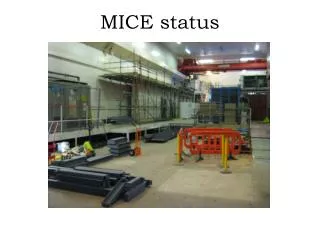
Beamline Support Rails
Beamline Schedule • ISIS Shutdown • First indication during Osaka meeting • Now confirmed: • Starts: 22nd December 2006 • Ends: 31st August 2007 • Additional shutdown: • Mid Oct-mid November 2006 • Probably ditto in 2007 • Within schedule – little slack • Completion of the hall work: • waiting for feedback of key information • Stairs • Mezzanine (Hydrogen System & Access) • Platform (support for MICE) • Window for Solenoid Commissioning with Cryogenics
Target • Focus of recent work has been assembly tests at RAL last week. • Review of components • Results of tests • Preliminary follow-up plans • Components: • Stator body • Ceramic tube • Glass readout tube • Target shuttle • Ceramic bearings • Electronics • Frame, jack, bellows, gate-valve
Target Assembly Test 24th-28th April • First time many parts came together: • Stator first connected to electronics 20th • Glass readout tube assembled 21st • Target shuttle finished morning of 24th • Some RAL parts and flanges not previously assembled. Still digesting results of last week! Despite problems, a lot was learned. • Practical details of assembly for first time. • Improved design of major components. • No proper vacuum tests. • No reliability or vibration tests. • Review (with ISIS) 16th May. • Will repeat assembly in hall. • Unlikely to install in ISIS for June – perform thorough off-line checks for October access.
Tracker Mechanical • Station Assembly: • Receive doublet-layers from FNAL • Visual inspection of the doublet-layers for any damage caused in transit • Align the doublet-layers on a vacuum chuck • Bundle seven fibres with rubber sleeves (QA) • Thread the bundle into a station connector (QA) • Put the vacuum chuck on an assembly jig • Fix a carbon-fibre station to the assembly jig • Glue the doublet-layers to carbon-fibre station • Attach doublet-layers connectors to the carbon-fibre station • Cut the fibres • Pot the fibres • Polish the fibres
Tracker Installation Tracker installation procedure presented at Tracker Review
KEK Analysis • Light yield is estimated by fitting the peak with gaussian. • Measured light yield is similar to the result of cosmic-ray test. This peak is caused by ADC saturation.
Comparison between KEK and Cosmic Ray Analyses • KEK beam test was performed in the fall of 2006. • Stability of VLPC are checked. • Pedestal peak is within 1 count, • Pedestal width is within 1-2%, • Gain is stable within 2%, and • Noise rate is within 5-8%. • Light yield and efficiency are studied with 3GeV/c pion beam without B-Field.
Scanning table Plane held on vacuum chuck LED and collimation and focussing system Scanning system: Tracker QA
Bundle fibres up into sevens – do about 10 bundles. Hold the fibres together with a rubber sleeve (already used to make the prototype) 7 fibres Place the bundles in a “comb” to hold them together and in place For these pictures 370nm was used throughout Bundling QA
Once the station connectors have been cut and polished. At this stage we measure light output. We will also make this measurement on the old stations which have been disassembled – this will allow us to validate the UV measurements against the test beam results Fibre Imaging
Hitachi U4100 sample compartment Detectors & integrating sphere Measure effect of UV irradiation on the fibres. Using high performance photometer Aperture Compartment modified to take optical rails and other components High precision fibre launcher Effect of UV on Fibres
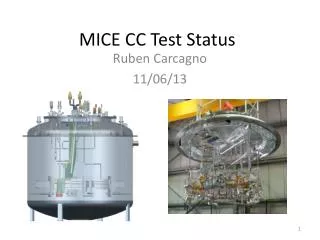
Tracker Cryo • MICE VLPC Cryo • 2 – 1024 Ch VLPC Cassettes in each system • Two systems per tracker- 4 Total for MICE + 1 Test Stand • Sumitomo GM Cryocooler • Cold-end operating point at approximately 7K • Cassette Gas system • Lid Heater and temp control circuitry • Vacuum pump
Cryostat Performance • Typical Cooldown
Temperature Control • Two stage Control • Heat applied to 2nd stage of cryo-cooler (7K) • Commercial Oxford temperature controller • Heaters in cassette (1 per module) control to final set point (9K) • System controls to better than 10 mK • Spec – 50 mK • However running with 50Hz power (KEK), left cassette heaters were barely on – almost no control from cassette • Thermal link 1 Count=1 mK
Cryo Status & Plans • The Prototype MICE VLPC cryo-system has been operated successfully for many months both at Fermilab and KEK • All design specs have been met except for a left-right temperature asymmetry • Thermal link design has been modified • This will be tested as soon as the Fermilab shutdown is over (June 06) • Cryo-coolers have been delivered • Cryostat parts are on order – expected delivery is mid-June 06. • All systems will be assembled, tested, and commissioned by the end of the calendar year
AFEIIt Status • The AFE IIt pre-production boards (15) have been tested to D0 spec • The first boards came up very quickly • In about 1 hour • No green wires! • TriPt testing is done • Yield is about 80% • More than enough chips for D0 + MICE + Spares for both experiments • Plus second pass could yield more • Production Order released April 18th • About 14 week lead for delivery of all boards • But many will arrive earlier • The critical issue for MICE is MICE-specific firmware development for AFE IIt • NOT a Trivial amount of work
AFEIIt Test Stands • The MICE IIT group has assembled an AFE test stand and will be responsible for testing left hand production boards • Part of Negotiated agreement that led to D0’s donation of AFE IIt boards to MICE • In Addition an AFE IIt test stand has been assembled at RAL • Board maintenance • Firmware development
Results from Preliminary Test • Conditioning started in late February 2006 with • Flat copper windows (plates) with Ti-N coatings • RF diagnostics • Good vacuum ~ high 10-9 Torr • Without an external magnetic field, the cavity conditioned very quietly and quickly to reach ~ 16 MV/m • Limited by available RF power. • Test plan being developed: • External magnetic fields • Achievable gradients vs magnetic field • Curved Be windows.
Sr90 trigger aerogel reflector cone 8” pmt Sr90b Source
CKOVI Road Map Summer ‘06 = 1 @ FNAL1x1x1 modulewhite reflectorMeasure pe yields ModelRayleigh Scattering Scattering vs Absorption~ 0Transmission vs Aperture 3x3 or 4x4 Fall- 06Mechanical fabrication Reflectors/Cones Spring ‘07Aerogel purchaseBegin Assembly CKV01 Summer ‘07
DAQ & Frascati Test Beam • Preparation for the test of PID detector components and potential front end electronics at a test beam at Frascati in the summer. • Stand alone DAQ is being built for this (not reusing UniDAQ system developed for KEK tests). • Work being done at University of Geneva. • Stand alone, local DAQ • DAQ Reduced to minimum: Local Start/Stop of Runs (no remote Run Control -> no DAQ framework, no event building) Write data on local Disk Readout particle per particle No interrupts • VME-PCI interface: CAEN V2718 only • Limited number of FEE modules supported • TDC V1290 • QDC V972 • Only 2 Event types: • Particle Event • Calibration Event
Status (19th April 2006) • Manpower: J.S. Graulich and 1 undergraduate student • Software for V2718: 80% done • All fundamentals are done: Read and Write in A32/D32,D16 Read in BLT32, BLT64 Basic I/O Register (2 Inputs, 5 Outputs) • Software for V1290: 80% done • Only tested with V1190, should be easily transported to V1290 • Not fully commissioned yet • Software for V792: 40% done • Work in progress • Software for run control: 25% done • Working on User interface
First Results & TBD • Readout rate of V1190 • 27 Mbytes/sec in BLT64 -> 5 ms to read the full V1190 buffer memory (Readout of the tracker would require at least 40 Mbytes/sec… already obtained with BIT3 interface -> we might have to deal with 2 different interface. No impact for BTF) • I need some inputs • Define needs for calibration • Define needs for online monitoring • Define needs for other FEE modules • Tests of QDC FEE options will start in background • Organize transport of my PC… • When is the test beam ?