Download

1 / 32
350 likes | 848 Views
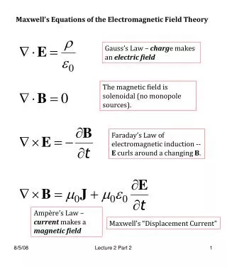
EE3321 ELECTROMAGNETIC FIELD THEORY. Week 10 Intrinsic Impedance Plane Wave Reflection Reflection, Transmission, Refraction Polarization. Intrinsic Impedance.

E N D
EE3321 ELECTROMAGNETIC FIELD THEORY Week 10 Intrinsic Impedance Plane Wave Reflection Reflection, Transmission, Refraction Polarization
Intrinsic Impedance • Any medium through which plane waves propagate have a property called intrinsic impedance or electromagnetic impedance, denoted by η. • The intrinsic impedance is analogous to the characteristic impedance of a cable in transmission line theory. • For a given frequency, the intrinsic impedance of a homogeneous material is given by the ratio of the E field phasor to the H field phasor.
Derivation • Consider a plane wave with fields E= Ei e jωt e –jkzax B= Bie jωt e –jkzay • Recall that these fields are related by – jkEi e jωt e –jkzay = – jω Bi e jωt e –jkzay
Derivation • Since H = B / μ it follows that – jkEi e jωt e –jkzay= – jωμ Hi e jωt e –jkzay kEi = ωμ Hi η = Ei/Hi = ωμ/k η = (μ/є)1/2
Propagation in Free Space • In free space μr = 1 and εr = 1. • Therefore the intrinsic impedance of free space ηo is given by ηo = 120 π which is approximately 377 Ω.
Complex Media • For a region with slight electrical conductivity (σ > 0, e.g. seawater), the equation becomes • This means that the E and H fields will be out of phase. • Exercise: What is the intrinsic impedance of a perfect conductor?
Plane Wave Reflection • When a plane wave passes from one dielectric medium (A) to another medium (B) with different intrinsic impedance, a fraction of its energy will be reflected and the remainder will be transmitted through the interface. • In this case, a reflection coefficient is used to describe the amplitude of the reflected part of the wave relative to the amplitude of the incident wave. The arrows indicate the direction of propagation
Reflection Coefficient • In particular, the reflection coefficient is the complex ratio of the electric field phasor of the reflected wave (E− ) to that of the incident wave (E+ ). • This is typically represented with a Γ (capital gamma) and can be written as:
Reflection Coefficient • Let the intrinsic impedances of the first and second media be η1 and η2, respectively. • At normal incidence the reflection coefficient of medium 2 relative to 1 is given by • Exercise: A plane wave hits a mirror at normal incidence. Determine the reflection coefficient.
Derivation • Reflected wave Er = Er e jωt e jkzax Hr = Hr e jωt e jkzay and η1 = - Er /Hr • Incident wave Ei= Ei e jωt e –jkzax Hi= Hi e jωt e –jkzay and η1= Ei/ Hi
Derivation • At the interface, the components of the electric field and magnetic field parallel to the surface must be continuous. • Consequently the following boundary condition must be satisfied: Ei+ Er = EtEi+ ΓEi = Et Hi+ Hr = Ht Ei/η1 – ΓEi/η1 = Et/η2 • This yields (1 – Γ)/η1 = (1 + Γ)/ η2 Γ = (η2 – η1) / (η2 + η1)
Perfect Reflection • When the electric field Eiis incident upon a perfectly conducting plate located a z = 0, the reflected field is Er= ΓEi e +jωt e +jkzx. The total field in region 1 E1= Ei + Er = Ei e +jωt (e –jkz + Γe+jkz) x • Since Γ = –1, the expression simplifies to E1= Ei + Er = Ei e +jωt (e –jkz– e +jkz) x E1= – 2jEi e +jωt sin (kz) x • Taking of the real part of E1 yields E1= 2Ei sin (ωt) sin (kz) x
Standing Wave • Exercise: Derive an expression for the total electric field if the reflection coefficient is Γ = 1.
Example • Standing Wave in a Microwave Oven
Microwave Oven • Consider the stationary electric field in a microwave oven: E= Eo e jωtsin (kz) axV/ m • The oven operates at a typical frequency of 2.45 GHz. The width of the oven W is 2.5 λ. • The electric field is zero on the side walls of the oven (i.e. at z = 0 and z = W).
Exercise • What is the width of the oven? • Is this a traveling wave or a standing wave? • What are the boundary conditions in the oven? • How many hot spots are there? • Where is |E| the strongest? In other words, where do you put the turkey?
Transmission Coefficient • The transmission coefficient τ is used when a plane wave encounters a change in the intrinsic impedance. • The transmission coefficient describes the amplitude of the transmitted wave relative to the incident wave. • The transmission coefficient is a measure of how much of an electromagnetic wave passes through a surface. • The transmission coefficient τ is defined as the ratio of the transmitted electric field to the ratio of the incident electric field.
Derivation • When the electric field Ei is incident upon a surface located a z = 0, the reflected field is Et= τ Eo e +jωt e –jkzx. • At the interface, the component of the electric field parallel to the surface must be continuous. • Consequently the following boundary condition must be satisfied: Ei(0) + Er(0) = Et(0) Ei+ ΓEi = τ Ei or1 + Γ = τ
Oblique Incidence • When an electromagnetic field moves from a medium of a given refractive index n1 into a second medium with refractive index n2, both reflection and refraction of the plane wave may occur. • An incident plane wave PO strikes at point O the interface between two media of refractive indexes n1 and n2. • Part of the wave is reflected as wave OQ and part refracted as ray OS. The angles that the incident, reflected and refracted waves make to the normal of the interface are given as θi, θr and θt, respectively.
Law of Reflection • The law of reflection states that the direction of the incident plane wave and the direction of the reflected plane wave make the same angle with respect to the surface normal. • That is, the angle of incidence equals the angle of reflection: θi= θr • Exercise: An electromagnetic plane wave is reflected by a perfect conductor. The angle of incidence is 45o. What percentage of the wave will be reflected at 30o?
Law of Refraction • Snell's law (also known as Descartes' law or the law of refraction) describes the relationship between the angles of incidence and refraction, when referring an electromagnetic wave, passing through a boundary between two different isotropic media, such as water and glass.
Law of Refraction • The law says that the ratio of the sines of the angles of incidence and of refraction is a constant that depends on the media. • The refraction of an electromagnetic wave occurs at the interface between two media of different refractive indices, with n2 > n1. • Since the velocity is lower in the second medium (v2 < v1), the angle of refraction θ2 is less than the angle of incidence θ1. • That is, the ray in the higher-index medium is closer to the normal.
Total Internal Reflection • When light moves from a dense to a less dense medium, such as from water to air, Snell's law cannot be used to calculate the refracted angle when the resolved sine value is higher than 1. • At this point, light is reflected in the incident medium, known as internal reflection. • Before the ray totally internally reflects, the light refracts at the critical angle; it travels directly along the surface between the two refractive media, without a change in phases like in other forms of optical phenomena.
Critical Angle • In order to calculate the critical angle, let θ2 = 90o and solve for θcrit: • When θ1 > θcrit, no refracted ray appears, and the incident ray undergoes total internal reflection from the interface medium.
Exercise • The index of refraction of water at optical wavelengths is approximately 1.33. • Suppose that a swimmer is underwater looking up at the water-air interface. • Determine the minimum angle at which she starts seeing the bottom of the pool reflected on the interface.
Polarization • Polarization is a property of waves that describes the orientation of their oscillations. • A polarizing filter, such as a pair of polarizing sunglasses, can be used to observe this effect by rotating the filter while looking through it at the reflection off of a distant horizontal surface. • At certain rotation angles, the reflected light will be reduced or eliminated.
Polarized Fields • For a simple harmonic wave, where the amplitude of the electric vector varies in a sinusoidal manner in time, the two components have exactly the same frequency: Ex= Exexp [ jθx ] exp [ j(ωt – kzz) ]ax Ey= Eyexp [ jθy ] exp [ j(ωt – kzz) ]ay • The two components may not have the same amplitude: Ex≠ Ey • The two components may not have the same phase, that is they may not reach their maxima and minima at the same time: θx ≠ θy
Linear Polarization • In the figure below, the E field is propagating in the + z direction. • The field has two components Exand Ey. • The components are both in phase and orthogonal (perpendicular) to each other.
Circular Polarization • In the case of circular polarization, the two orthogonal components Ex and Ey have exactly the same amplitude and are exactly ninety degrees out of phase. • In this case one component is zero when the other component is at maximum or minimum amplitude.
Handedness • The direction the field rotates in, depends on which of the two phase relationships exists. • Depending on which way the electric vector rotates these cases are called • right-hand circular polarizationand • left-hand circular polarization. • In electrical engineering, the rotation is defined as seen from the source, such as from a transmitting antenna.
Elliptical Polarization • More generally, the two components are not in phase and do not have the same amplitude. • In this case the polarization is called elliptical polarization because the electric vector traces out an ellipse in the plane (the polarization ellipse).
Homework • Read book sections 7-1, 7-2, 7-3, 8-1, 8-2 • Solve end-of-chapter problems 7.1, 7.5, 7.10, 8.1, 8.17