Download
1 / 49
490 likes | 492 Views
Barry Barish FALC Fermilab 4-Nov-05. GDE Report to FALC Status and Plans. ILC Polarized Electron Source. The ITRP Recommendation. We recommend that the linear collider be based on superconducting rf technology

E N D
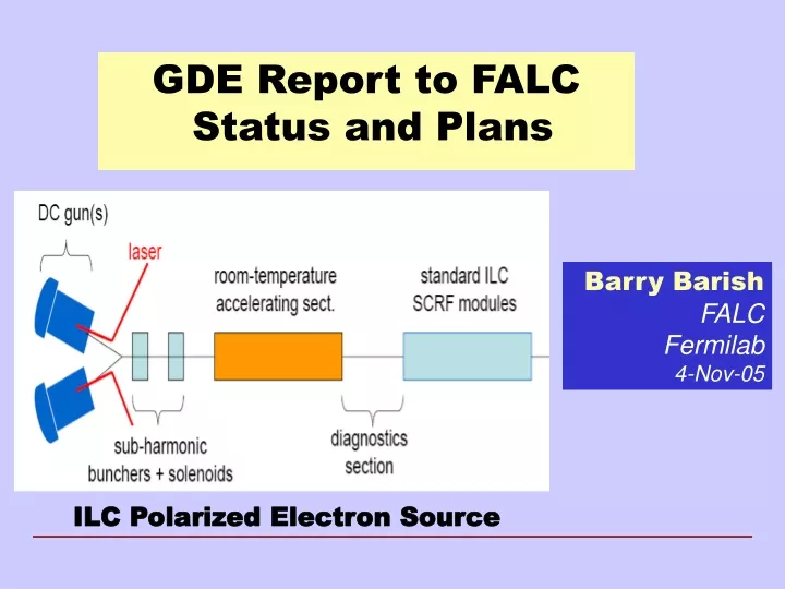
Barry Barish FALC Fermilab 4-Nov-05 GDE Report to FALC Status and Plans ILC Polarized Electron Source
The ITRP Recommendation • We recommend that the linear collider be based on superconducting rf technology • This recommendation is made with the understanding that we are recommending a technology, not a design. We expect the final design to be developed by a team drawn from the combined warm and cold linear collider communities, taking full advantage of the experience and expertise of both(from the Executive Summary). FALC - Fermilab
SCRF Technology Recommendation • The recommendation of ITRP was presented to ILCSC & ICFA on August 19, 2004 in a joint meeting in Beijing. • ICFA unanimously endorsed the ITRP’s recommendation on August 20, 2004 FALC - Fermilab
The Community Self-Organized Nov 13-15, 2004 FALC - Fermilab
Self Organization following Technology Decision • 1st ILC workshop at KEK November 2005 • ILCSC forms 5 technical WG + 1 communications and outreach WG • WG1 Parameters & General Layout • WG2 Main Linac • WG3 Injectors • WG4 Beam Delivery & MDI • WG5 High gradient SCRF • WG6 Communications FALC - Fermilab
WG1 Parms & layout WG2 Linac WG3 Injectors WG4 Beam Delivery WG5 High Grad. SCRF WG6 Communications WG1 LET beam dynamics WG2 Main Linac WG3a Sources WG3b Damping Rings WG4 Beam Delivery WG5 SCRF Cavity Package WG6 Communications Evolution by Snowmass Birth of the GDE and Preparation for Snowmass FALC - Fermilab
Global Design Effort • The Mission of the GDE • Produce a design for the ILC that includes a detailed design concept, performance assessments, reliable international costing, an industrialization plan , siting analysis, as well as detector concepts and scope. • Coordinate worldwide prioritized proposal driven R & D efforts (to demonstrate and improve the performance, reduce the costs, attain the required reliability, etc.) FALC - Fermilab
Chris Adolphsen, SLAC Jean-Luc Baldy, CERN Philip Bambade, LAL, Orsay Barry Barish, Caltech Wilhelm Bialowons, DESY Grahame Blair, Royal Holloway Jim Brau, University of Oregon Karsten Buesser, DESY Elizabeth Clements, Fermilab Michael Danilov, ITEP Jean-Pierre Delahaye, CERN, Gerald Dugan, Cornell University Atsushi Enomoto, KEK Brian Foster, Oxford University Warren Funk, JLAB Jie Gao, IHEP Terry Garvey, LAL-IN2P3 Hitoshi Hayano, KEK Tom Himel, SLAC Bob Kephart, Fermilab Eun San Kim, Pohang Acc Lab Hyoung Suk Kim, Kyungpook Nat’l Univ Shane Koscielniak, TRIUMF Vic Kuchler, Fermilab Lutz Lilje, DESY Tom Markiewicz, SLAC David Miller, Univ College of London Shekhar Mishra, Fermilab Youhei Morita, KEK Olivier Napoly, CEA-Saclay Hasan Padamsee, Cornell University Carlo Pagani, DESY Nan Phinney, SLAC Dieter Proch, DESY Pantaleo Raimondi, INFN Tor Raubenheimer, SLAC Francois Richard, LAL-IN2P3 Perrine Royole-Degieux, GDE/LAL Kenji Saito, KEK Daniel Schulte, CERN Tetsuo Shidara, KEK Sasha Skrinsky, Budker Institute Fumihiko Takasaki, KEK Laurent Jean Tavian, CERN Nobu Toge, KEK Nick Walker, DESY Andy Wolski, LBL Hitoshi Yamamoto, Tohoku Univ Kaoru Yokoya, KEK 49 members GDE Members Americas 16 Europe 21 Asia 12 FALC - Fermilab
Starting Point for the GDE Superconducting RF Main Linac FALC - Fermilab
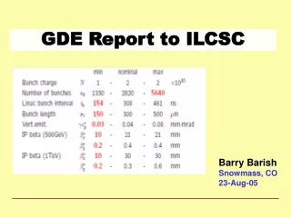
Parameters for the ILC • Ecm adjustable from 200 – 500 GeV • Luminosity ∫Ldt = 500 fb-1 in 4 years • Ability to scan between 200 and 500 GeV • Energy stability and precision below 0.1% • Electron polarization of at least 80% • The machine must be upgradeable to 1 TeV FALC - Fermilab
GDE Structure and Organization • Executive Committee for Baseline Configuration • GDE Director • Barish • Regional Directors • Dugan – Americas • Foster – Europe • Takasaki – Asia • Accelerator Leaders • Yokoya - Asia • Raubenheimer - Americas • Walker - Europe • Responsible for decisions and documentation for the Baseline Configuration Document (BCD) FALC - Fermilab
GDE Structure and Organization • GDE Groups • Design / Cost Engineers • Shidara – Asia • Bialowons – Europe • Garbincius – Americas • Siting, Civil Construction and Infrastructure • Baldy - Europe • Enomoto – Asia • Kuchler – Amercas • Physics / Detectors (WWS chairs) • Brau - Americas • Richard - Europe • Yamamoto - Asia • Accelerator Experts (34 GDE members) FALC - Fermilab
GDE Organizational Evolution for RDR • Selected additions to the GDE following the BCD completion having needed skills in design, engineering, costing, etc • Change Control Board • The baseline will be put under configuration control and a Board with a single chair will be created with needed expertise. • R&D Board • A GDE Board will be created to evaluate, prioritize and coordinate the R&D program in support of the baseline and alternatives with a single chair • Design / Cost Board • A GDE Board with single chair will be established to coordinate the reference design effort, including coordinating the overall model for implementing the baseline ILC, coordinating the design tasks, costing, etc. FALC - Fermilab
2005 2006 2007 2008 2009 2010 CLIC Global Design Effort Project LHC Physics Baseline configuration Reference Design The GDE Plan and Schedule Technical Design ILC R&D Program Expression of Interest to Host International Mgmt
GDE Begins at Snowmass 670 Scientists attended two week workshop at Snowmass FALC - Fermilab
Self Organization following Technology Decision • 1st ILC workshop at KEK November 2005 • ILCSC forms 5 technical WG + 1 communications and outreach WG • WG1 Parameters & General Layout • WG2 Main Linac • WG3 Injectors • WG4 Beam Delivery & MDI • WG5 High gradient SCRF • WG6 Communications FALC - Fermilab
WG1 Parms & layout WG2 Linac WG3 Injectors WG4 Beam Delivery WG5 High Grad. SCRF WG6 Communications WG1 LET beam dynamics WG2 Main Linac WG3a Sources WG3b Damping Rings WG4 Beam Delivery WG5 SCRF Cavity Package WG6 Communications Evolution by Snowmass Birth of the GDE and Preparation for Snowmass FALC - Fermilab
WG1 Parms & layout WG2 Linac WG3 Injectors WG4 Beam Delivery WG5 High Grad. SCRF WG6 Communications WG1 LET beam dynamics WG2 Main Linac WG3a Sources WG3b Damping Rings WG4 Beam Delivery WG5 SCRF Cavity Package WG6 Communications GG1 Parameters & Layout GG2 Instrumentation GG3 Operations & Reliability GG4 Cost Engineering GG5 Conventional Facilities GG6 Physics Options Enter the GDE - Snowmass Birth of the GDE and Preparation for Snowmass Introduction of Global Groups transition workshop → project FALC - Fermilab
WG1 LET bdyn. WG2 Main Linac WG3a Sources WG3b DR WG4 BDS WG5 Cavity GG1 Parameters GG2 Instrumentation GG3 Operations & Reliability GG4 Cost & Engineering GG5 Conventional Facilities GG6 Physics Options GDE Organization for Snowmass Technical sub-system Working Groups Provide input Global Group FALC - Fermilab
Goals of the Snowmass Workshop • Recommendations for the Baseline Configuration • Identify - Alternative Configurations • Identify R&D • To support the baseline • To develop the alternatives • Priorities for detector R&D FALC - Fermilab
Guidance for Baseline Configuration Baseline: A forward looking configuration which we are reasonably confident can achieve the required performance and can be used to give a reasonably accurate cost estimate by mid-end 2006 in a “Reference Design Report.” FALC - Fermilab
What are Alternatives and Why? Alternates: Technologies or concepts, which may provide a significant cost reduction, improved performance (or both), but which will not be mature enough to used in baseline by end 2006Alternatives will be part of the RDR, will form an important element in the R&D program and are the key to evolving the design FALC - Fermilab
Baseline Configuration Document • Our ‘Deliverable’ by the end of 2005 • A structured electronic document • Documentation (reports, drawings etc) • Technical specs. • Parameter tables • … • A ‘printable / readable’ summary document (~100 pages) FALC - Fermilab
Structure of the BCD Summary-like overview for those who want to understand the choice and the why Technical documentation of the baseline, for engineers and acc. phys. making studies towards RDR FALC - Fermilab
Alternatives Section(s) NoteACD is part of the BCD FALC - Fermilab
Design Approach • Create a baseline configuration for the machine • Document a concept for ILC machine with a complete layout, parameters etc. defined by the end of 2005 • Make forward looking choices, consistent with attaining performance goals, and understood well enough to do a conceptual design and reliable costing by end of 2006. • Technical and cost considerations will be an integral part in making these choices. • Baseline will be put under “configuration control,” with a defined process for changes to the baseline. • A reference design will be carried out in 2006. I am proposing we use a “parametric” design and costing approach. • Technical performance and physics performance will be evaluated for the reference design FALC - Fermilab
Parametric Approach • Parametric approach to design • machine parameters : a space to optimize the machine • Trial parameter space, being evaluated by subsystems • machine design : incorporate change without redesign; incorporates value engineering, trade studies at each step to minimize costs FALC - Fermilab
Approach to ILC R&D Program • Proposal-driven R&D in support of the baseline design. • Technical developments, demonstration experiments, industrialization, etc. • Proposal-driven R&D in support of alternatives to the baseline • Proposals for potential improvements to the baseline, resources required, time scale, etc. • Develop a prioritized DETECTOR R&D program aimed at technical developments needed to reach combined design performance goals FALC - Fermilab
The Key Decisions Critical choices: luminosity parameters & gradient FALC - Fermilab
Making Choices – The Tradeoffs Many decisions are interrelated and require input from several WG/GG groups FALC - Fermilab
Cost Breakdown by Subsystem Civil SCRF Linac FALC - Fermilab
TESLA Cavity ~1m 9-cell 1.3GHz Niobium Cavity Reference design: has not been modified in 10 years FALC - Fermilab
How Costs Scale with Gradient? 35MV/m is close to optimum Japanese are still pushing for 40-45MV/m 30 MV/m would give safety margin Relative Cost Gradient MV/m C. Adolphsen (SLAC) FALC - Fermilab
Cavity Fabrication FALC - Fermilab
Gradient Results from KEK-DESY collaboration must reduce spread (need more statistics) single-cell measurements (in nine-cell cavities) FALC - Fermilab
Improved Fabrication FALC - Fermilab
Improved ProcessingElectropolishing FALC - Fermilab
Improved Cavity Shapes FALC - Fermilab
Cavity R&D Fabrication from large grain Nb discs May remove the need for electropolishing ( cost!) FALC - Fermilab
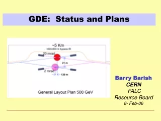
ILC Siting and Conventional Facilities • The design is intimately tied to the features of the site • 1 tunnels or 2 tunnels? • Deep or shallow? • Laser straight linac or follow earth’s curvature in segments? • GDE ILC Design will be done to samples sites in the three regions • North American sample site will be near Fermilab • Japan and Europe are to determine sample sites by the end of 2005 FALC - Fermilab
1 vs 2 Tunnels • Tunnel must contain • Linac Cryomodule • RF system • Damping Ring Lines • Save maybe $0.5B • Issues • Maintenance • Safety • Duty Cycle FALC - Fermilab
Possible Tunnel Configurations • One tunnel of two, with variants ?? FALC - Fermilab
ILC Civil Program Civil engineers from all three regions working to develop methods of analyzing the siting issues and comparing sites. The current effort is not intended to select a potential site, but rather to understand from the beginning how the features of sites will effect the design, performance and cost FALC - Fermilab
How and when to involve industry? • Large Scale Project Characterization • Large Project Management • Precision Engineering • International Coordination • Costing • Industrialization • Civil Construction & Infrastructure • Cryogenics • Superconducting RF structures, couplers, etc • Electronics and Control Systems • Large Scale Computing FALC - Fermilab
Since Snowmass • Summaries from Working Groups and Global Groups are posted on the ILC Website • Analysis and Recommendations of the 40+ Decisions posted on the ILC Website • GDE Executive Committee met at SLAC 22-Sept to assess Snowmass results, make plans to produce a “strawman” baseline by mid-November • Planning done in the context of organizational approach and structures for next year to produce the RDR FALC - Fermilab
From Snowmass to a Baseline 2005 Snowmass August September October November December WW/GG summaries Response to list of 40+ decisions All documented ‘recommendations available on ILC Website (request community feedback) Review by BCD EC BCD EC publishes‘strawman’ BCD BCD Executive Committee: BarishDugan, Foster, Takasaki Raubenheimer, Yokoya, Walker Public Review Frascati GDE meeting FALC - Fermilab
Baseline Configuration Document Review Process • BCD executive committee will monitor BCD progress • Review WG/GG summary write-ups (recommendations) • Review each question on the list of 40+ decisions • BCD EC will identify and solicit needed additional input • additional expertise from ILC / GDE community • Strawman BCD available mid-November • Presentation of strawman BCD at Frascati GDE meeting (Dec. 10-12) • Final agreed BCD to be documented by end of 2005 • Final BCD becomes property of ‘change control board’ in early 2006 • Begin the Reference Design to be completed by end of 2006 FALC - Fermilab
2005 2006 2007 2008 2009 2010 CLIC Global Design Effort Project LHC Physics Baseline configuration Reference Design The GDE Plan and Schedule Technical Design ILC R&D Program Expression of Interest to Host International Mgmt