Download
1 / 30
360 likes | 541 Views
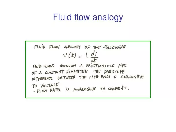
Fluid flow analogy. Power and energy in an inductor. Capacitor v-i equation. Capacitor Power equation. Capacitor : power and energy. Capacitor : power and energy. The self- and mutually induced voltages. The self- and mutually induced voltages. 7-1 . The natural response of an RL circuit.

E N D
7-1 . The natural response of an RL circuit • Independent current source IS . • The switch has been closed for a “long time”. • L di/dt = 0 at t <0 (before the release of stored energy) ; the inductor appears a s a short circuit . • No current in R0 and R ; all the current appears in L branch .Finding v(t) and i(t) for t>=0 .
LR Circuits Equations Expressions for the current
Time constant(1% of the initial value at five time constants)-less than 5 constants : the transient response- exceeds 5 constants : steady- state response
Determination of time constant Equations (cont’d) Time constant (cont’d)
7-2 The natural response of an RC circuit • An RC circuit is analogous to an RL circuit • The switch has been in the position for a long time such that all the elements in the circuit reach a steady-state condition . • A source voltage exists between the terminals. • Circuit after switching is shown in Fig. 7-11 .
Circuit consisting of R, C and Vg Expression for the voltage