Download
1 / 21

E N D
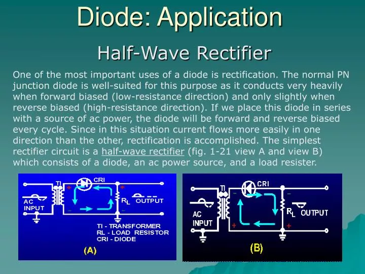
Diode: Application One of the most important uses of a diode is rectification. The normal PN junction diode is well-suited for this purpose as it conducts very heavily when forward biased (low-resistance direction) and only slightly when reverse biased (high-resistance direction). If we place this diode in series with a source of ac power, the diode will be forward and reverse biased every cycle. Since in this situation current flows more easily in one direction than the other, rectification is accomplished. The simplest rectifier circuit is a half-wave rectifier (fig. 1-21 view A and view B) which consists of a diode, an ac power source, and a load resister. Half-Wave Rectifier
Diode: Application The transformer (T1) in the figure provides the ac input to the circuit; the diode (CR1) provides the rectification; and the load resistor (RL) serves two purposes: it limits the amount of current flow in the circuit to a safe level, and it also develops the output signal because of the current flow through it.
Rectification Before describing how this circuit operates, the definition of the word "load" as it applies to power supplies must be understood. Load is defined as any device that draws current. A device that draws little current is considered a light load, whereas a device that draws a large amount of current is a heavy load. Remember that when we speak of "load," we are speaking about the device that draws current from the power source. This device may be a simple resistor, or one or more complicated electronic circuits
Rectification During the positive half-cycle of the input signal (solid line) in figure view A, the top of the transformer is positive with respect to ground. The dots on the transformer indicate points of the same polarity. With this condition the diode is forward biased, the depletion region is narrow, the resistance of the diode is low, and current flows through the circuit in the direction of the solid lines. When this current flows through the load resistor, it develops a negative to positive voltage drop across it, which appears as a positive voltage at the output terminal.
Rectification However, if the diode is reversed as shown in view B of figure , a negative output voltage would be obtained. This is because the current would be flowing from the top of RL toward the bottom, making the output at the top of RL negative with respect to the bottom or ground. Because current flows in this circuit only during half of the input cycle, it is called a half-wave rectifier.
Capacitor Filter Circuit Since practical values of C1 and RL ensure a more or less gradual decrease of the discharge voltage, a substantial charge remains on the capacitor at the time of the next half cycle of operation. As a result, no current can flow through the diode until the rising ac input voltage at the anode of the diode exceeds the voltage on the charge remaining on C1. The charge on C1 is the cathode potential of the diode. When the potential on the anode exceeds the potential on the cathode (the charge on C1), the diode again conducts, and C1 begins to charge to approximately the peak value of the applied voltage.
Capacitor Filter Circuit Operation of the simple capacitor filter using a full-wave rectifier is basically the same as that discussed for the half-wave rectifier. Referring to figure 4-18, you should notice that because one of the diodes is always conducting on. either alternation, the filter capacitor charges and discharges during each half cycle. (Note that each diode conducts only for that portion of time when the peak secondary voltage is greater than the charge across the capacitor.)
Voltage Doubler When A is positive, D1 is forward biased and charges C1 to the peak voltage, as in diagram 2. D2 is reverse biased and does not conduct. When A goes negative, D1 is reverse biased and does not conduct. D2 is forward biased and charges C2 to the peak voltage, as in diagram 3.
Voltage Doubler simulation circuit