Download
1 / 28
330 likes | 778 Views
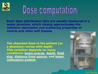
Absolute Dose Measurement. TG-51 : Photons. D Q,water is the absorbed dose to water at the point of measurement of the ion chamber placed under reference conditions for a clinical beam with beam quality Q. TG-51 : Photons.

E N D
TG-51 : Photons DQ,water is the absorbed dose to water at the point of measurement of the ion chamber placed under reference conditions for a clinical beam with beam quality Q.
TG-51 : Photons • D,wNCo is the absorbed-dose-to-water calibration factor traceable to national primary standards for the ion chamber used.
Photon Beam Quality (Q) • The beam quality Q is specified by the %dd(10)x. • %dd – Percent Depth Dose • (10)x – Photon component at a 10-cm depth for a field size of 10x10 cm2 on the surface of a phantom at SSD of 100 cm. • Photon energies < 10 MeV, %dd(10)x is the fractional depth dose at 10 cm depth, %dd(10). • Depth ionization curve can be treated as depth dose. • Be sure to shift the depth dose upstream by 0.6rcav. • rcav is the radius of the air cavity of the ion chamber.
Photon Beam Quality (Q) • Photon energies > 10 MeV, %dd(10)x is obtained by taking depth-dose measurements using a 1-mm lead foil placed 30 or 50 cm from the phantom surface and applying appropriate equation in the protocol. • %dd(10)x = [0.8905 + 0.00150 . %dd(10)Pb] . %dd(10)Pb • Foil at 50 cm, %dd(10)Pb ≥ 73% • %dd(10)x = [0.8116 + 0.00264 . %dd(10)Pb] . %dd(10)Pb • Foil at 50 cm, %dd(10)Pb ≥ 71% • If %dd(10)Pb is less than thresholds, %dd(10)x = %dd(10)Pb
Photon Beam Quality (Q) • No lead foil available? • %dd(10)x = 1.267%dd(10) – 20.0 • For 75% < %dd(10) ≤ 89% • %dd(10)x = %dd(10) • For %dd(10) ≤ 75% • Not recommended, but acceptable if unavoidable.
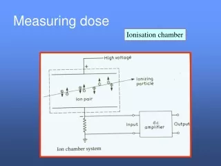
Ion Chamber Reading (M) • Point of measurement – the point at which absorbed dose is measured. • Cylindrical ion chambers – on the central axis of the cavity at the center of the active volume of the cavity. • Plane-parallel chamber – at the front (upstream side) of the air cavity at the center of the collecting region. • Mraw is the uncorrected ion chamber reading with the point of measurement at a depth d in water, for a given number of monitor units.
Ion Chamber Reading (M) • M : the fully corrected ion chamber reading. • M = Pion. PTP. Pelec. PPol. Mraw • Pion : recombination correction factor • PTP : temperature/pressure correction factor • Pelec : electrometer correction factor • Calibrated at ADCL for a specific scale • PPol : polarity correction factor
Recombination (Pion) • Pion : recombination correction factor • Pion is dependent on chamber design, pulse rate, and bias voltage. • Usually pulse rate is set for a particular dose rate, but measurements should be redone if pulse rate is changed for that dose rate. • Ion chambers with Pion > 1.05 should not be used because the uncertainty in the Pion value. • Bias voltage should not be above 300 V, again because theory starts to breaks down.
Recombination (Pion) • For continuous beams (i.e., 60Co) • For pulsed or scanned beams
Temperature/Pressure (PTP) • Standard conditions • Temperature: 22° C • Pressure 101.33 kPa (760 mmHg) • Wait 5-10 minutes after readings stabilize to assume equilibrium with environment. • Humidity in range of 20% to 80% not a factor.
Polarity (PPol) • Polarity effects vary with beam quality and other conditions such as cable position. • Measured with reference voltage of opposing bias.
Quality Conversion Factor (kQ) • kQ is the quality conversion factor which converts the calibration factor for a 60Co beam to that for a photon beam of quality Q. • kQ has been determined for numerous commercial ion chambers and varies with beam quality. • kQ = 1.000 for 60Co by definition. • kQ have not been determined for plane-parallel chambers because of insufficient information about wall correction factors in photon beams other than 60Co.
TG-51 Electrons • M – raw measured ionization reading • kQ – beam quality conversion factor • D,wNCo60 – absorbed-dose to water calibration factor
Beam Quality Conversion Factor • grPQ – gradient correction factor – the component of kQ that is dependent on the ionization gradient at the POM. • k50 – component of kQ in an electron beam that is independent of the ionization gradient at the POM (point of measurement). • R50k' – electron quality conversion factor • kecal – photon-electron conversion factor
Depth of 50% dose (R50) • First measure ionization curve • Remember to shift depth dose upstream by 0.5rcav when using a cylindrical ion chamber. • Locate depth of 50% ionization (I50)
Detectors for TG-51 Electrons • R50 ≤ 2.6 cm (6 MeV or less) • Must use plane-parallel chamber • R50 ≤ 4.3 cm (10 MeV or less) • Plane-parallel chamber is preferred • R50 > 4.3 cm • Cylindrical or plane-parallel chamber can be used
Reference Condition • Reference depth dref = 0.6R50 – 0.1 cm • POM of chamber is placed at dref • SSD = 100 cm • For R50 ≤ 8.5 cm, use a 10x10-cm2 field • For R50 > 8.5 cm, use a 20x20-cm2 field
Gradient Correction Factor grPQ • grPQ = 1.00 for plane-parallel chambers • Close to unity for cylindrical chambers in an electron beam of 10 MeV or less. • For cylindrical chambers:
R50k' – plane parallel chambers • Figure 6 and 8 gives r50k' as a function of R50 for various plane-parallel chambers. Figure 6. Low-energy electron beams Figure 8. High-energy electron beams
R50k' – plane parallel chambers • Analytical expression of curves in Figs. 6 and 8.
R50k' – cylindrical chambers • Figure 7 plots r50k' vs. R50 for various cylindrical chambers.
R50k' – cylindrical chambers • Analytical expression of curves in Figs. 6 and 8.
Photon-electron conversion factor • kecal determined for commercial chambers using beam quality R50 = 7.5 cm. • Cylindrical chambers • Table III lists kecal value for cylindrical chambers. • Plane-parallel chambers • Table II lists kecal value for plane-parallel chambers • It is recommended to cross-calibrate plane-parallel chambers with cylindrical chambers in a high-energy electron beam using equation 21 (item 8 on worksheet).
Absorbed dose at dmax • If dref does not occur at dmax on the depth dose curve, the reference output dose must be corrected to dmax. • Will happen for high-energy beams. • Example: dref = 95%, D(dmax) = D(dref)/0.95 • Use the depth-dose curve, not the depth-ionization curve. • Will require TG-25 protocol to determine stopping power ratios and Prepl as a function of depth if measured with ion chamber. • Can be measured directly with diode detector.