Download
1 / 76
760 likes | 863 Views
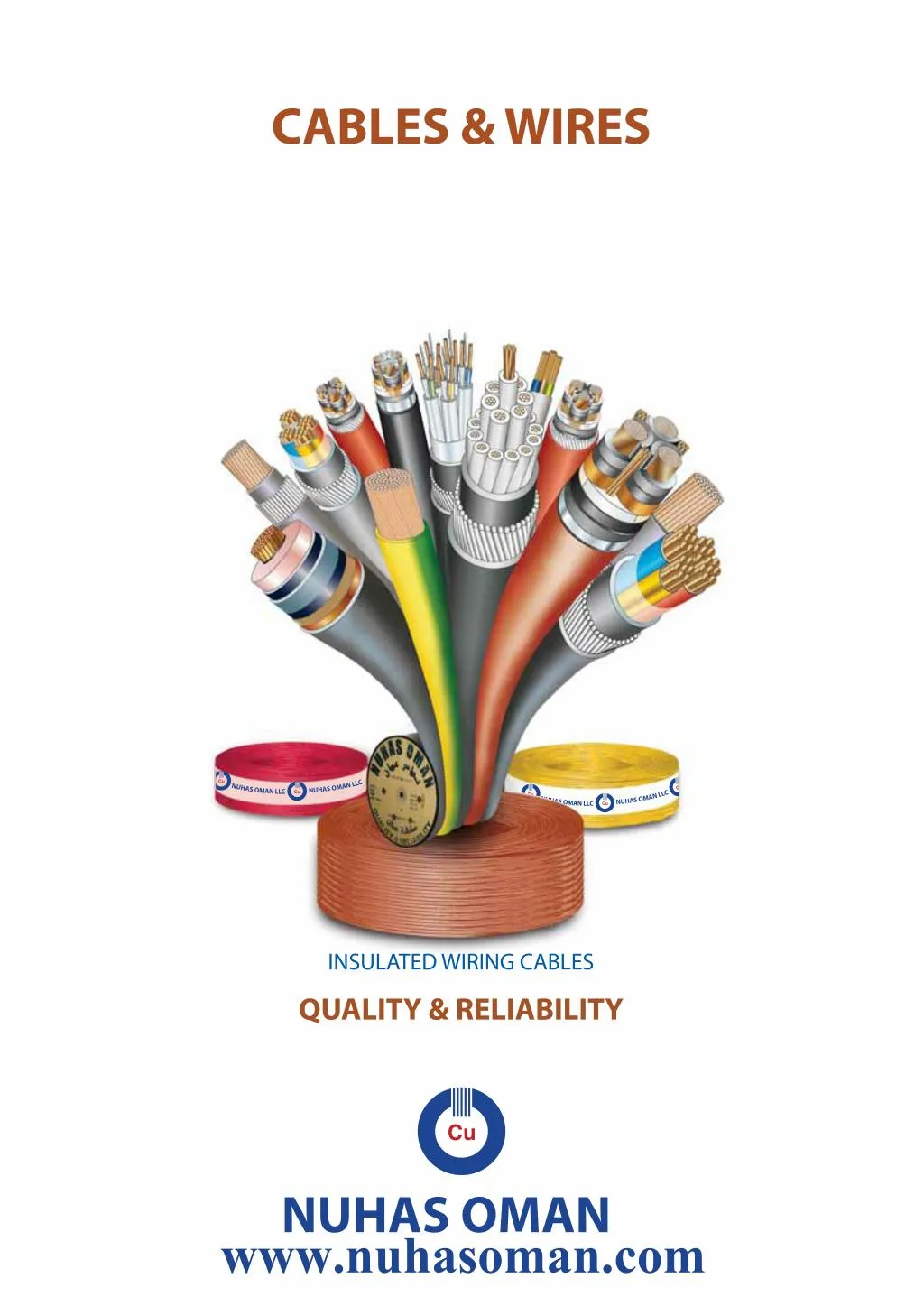
Nuhas Oman LLC, a member of the Al-Bahja Group of CompaniesThe company is committed to meet the challenges of the Domestic & Global markets for supply of world class Cables & Wires. Nuhas Oman's range of Cable products meet the requirements of a broad spectrum of applications including - Industrial, Power & Distribution, Ship Building and Offshore Platforms, Petrochemical, Oil & Gas, Aeronautical, Building & Construction, Instrumentation, Hospitals, Hotels, Entertainment & Security etc.<br><br>

E N D
??????????????? ?????????? www.nuhasoman.com ?
INTRODUCTION Nuhas Oman LLC, an integral part of The Al Bahja Group of Companies, is a Quality producer of: ???????????????????????????????????????? ??????????????????????????????????? ???????????????????????????????????? ??????????????????????????????????????????? ???????????????????????????????????????? ????????????????????????????? ???????????????????????????????????????? ?????????????????????????????? ??????????????????????????????? ??????????????????????????????? • HV, MV and LV Cables • Enamelled Copper Wires • Oxygen Free Continuous Cast Copper Wire Rods • Our state-of-the-art manufacturing facilities with cutting edge technology ensure that our products meet with highest quality standards. All our products utilize only OXYGEN FREE HIGH CONDUCTIVITY ELECTRONIC GRADE Copper produced through the Outokompu UPCAST technology, producing minimum 99.99% pure copper with oxygen content less than 5 ppm. The usage of ????????????????????????????????????? Drawn Copper Conductors ???????????????????????????????????????????? Our range of World-class HV, MV and LV Cables includes Single & Multi Core Armoured and Un-armoured Cables, Specialty, Control, Instrumentation and also LSF, FRLS, LSOH & Custom Cables to meet the requirements of a broad spectrum of applications ranging from ????????????????????????????????????????????????????? ????????????????????????????????????????????????????????????????????????????????????? The Cables are produced in compliance to the requirements of BS, IEC, VDE, ASTM, ICEA & UL specifications. The ???????????????????????????????? by acclaimed independent international certifying agencies confirming compliance to respective standards. Nuhas???????????????????????????????????????? that conform to relevant International standards and ???????? ???????????????????????????????????????????????????????????????? ? ??????????????????????????????????????????????????????????????????????????????????????????????? Our quality cycle encompasses raw material and consumable sourcing, in-process production controls and certification of finished goods prior to delivery. A well-equipped in-house quality assurance facility, manned by qualified professionals from the industry, ensures that all products delivered meet stringent quality controls and parameters. Our state-of-the-art laboratory is equipped to test as per relevant international standards as also to individual customer specifications. The company endeavours to cater to the domestic, regional and global markets while maintaining the sanctity of our pristine environment. ??????????????????????? is a continuing process at Nuhas Oman LLC and we at Nuhas Oman ceaselessly strive to achieve product excellence through TOTAL QUALITY MANAGEMENT to provide the best value to our customers. NUHAS OMAN – QUALITY & RELIABILITY. 1
SINGLE CORE PVC INSULATED CABLES H05V-U, H07V-U, H07V R BS 6004:2000 Type Standards In dry rooms, in apparatus, switch and distribution boards, for laying in conduit on and under plaster and on insulating supports above plaster Applications SINGLE CORE PVC INSULATED FLEXIBLE CABLES Construction 1) Oxygen Free Electronic Copper Conductor 2) PVC Insulation H05V-K, H07V-K Type Flexible wire, for protected installation in equipment and lighting fitting conduit or under plaster Applications BS 6004:2000 1) Fine stranded Oxygen Free Electronic copper wire 2) PVC Insulation Standards Construction Max. Operating Temperature: 70 º C Rated Voltage: 300/500 V (H05V-U) 450/750 V(H07V-U, H07V-R) Technical Data In rolls of 100 yards, spools, drums or as per customer requirements Packing Max. Operating Temperature: 70 0 C Rated Voltage: 300/500 V H05V-K 450/750 V H07V-K Technical Data In rolls of 100 yards, spools, drums or as per customer requirements Packing NOMINAL CROSS SECTION INSULATION THICKNESS MAX. OVERALL DIAMETER APPROX. NET WEIGHT STANDARD LENGTH CLASS OF COPPER CON- DUCTOR (mm 2 ) (mm Nominal) (mm) (kg/ km) CLASS OF COPPER CON- DUCTOR NOMINAL CROSS SECTION INSULATION THICKNESS MAX. OVERALL DIAMETER APPROX. NET WEIGHT STANDARD LENGTH H05V-U 300/ 500 V 0.50 0.75 Yards 100 100 100 1 1 1 0.6 0.6 0.6 2.3 2.5 2.7 9 11 14 (mm 2 ) (mm Nominal) (mm) (kg/ km) 1.0 H05V-K 300/ 500 V 0.5 0.75 1.0 Yards 100 100 100 H07V-U 450/ 750 V 5 5 5 0.6 0.6 0.6 2.5 2.7 2.8 9 11 14 1.5 2.5 4 6 1 1 1 1 0.7 0.8 0.8 0.8 3.2 3.9 4.4 5.0 21 32 47 66 100 100 100 100 H07V-K 450/ 750 V 1.5 2.5 4 6 H07V-R 450/ 750 V 5 5 5 5 0.7 0.8 0.8 0.8 3.4 4.1 4.8 5.3 21 32 47 66 100 100 100 100 Meters 300 300 1000 1000 1000 1000 1000 1000 1000 1000 1000 1.5 2.5 4 6 2 2 2 2 0.7 0.8 0.8 0.8 3.3 4.0 4.6 5.2 21 32 47 66 100 100 100 100 Meters 300 300 1000 1000 1000 1000 1000 1000 1000 1000 1000 1000 1000 1000 500 10 16 25 35 50 70 95 120 150 185 240 5 5 5 5 5 5 5 5 5 5 5 1.0 1.0 1.2 1.2 1.4 1.4 1.6 1.6 1.8 2.0 2.2 6.8 8.1 10.2 11.7 13.9 16.0 18.2 20.2 22.5 24.9 28.4 110 170 266 360 494 696 965 1203 1483 1852 2424 10 16 25 35 50 70 95 120 150 185 240 300 400 500 630 2 2 2 2 2 2 2 2 2 2 2 2 2 2 2 1.0 1.0 1.2 1.2 1.4 1.4 1.6 1.6 1.8 2.0 2.2 2.4 2.6 2.8 2.8 6.7 7.8 9.3 10.5 11.9 13.6 15.7 17.2 19.0 21.1 23.8 26.5 29.6 33.0 36.7 115 175 260 350 480 670 925 1150 1415 1775 2320 2895 3695 4720 6030 3 2
HEAT RESISTANT SINGLE CORE PVC INSULATED CABLES H07V2-R H07V2-U Type In dry rooms, in apparatus, switch and distribution boards, for laying in conduit on and under plaster and on insulating supports above plaster Applications BS 6004:2000 Standards HEAT RESISTANT SINGLE CORE PVC INSULATED FLEXIBLE CABLES Construction 1) Oxygen Free Electronic Copper Conductor 2) HR PVC Insulation H07V2K Type Flexible wire, for protected installation in equipment and lighting fitting conduit or under plaster Applications Max. Operating Temperature: 90 º C Rated Voltage: 450/750 V Technical Data In rolls of 100 yards, spools, drums or as per customer requirements Packing BS 6004:2000 Standards Construction 1) Fine stranded Oxygen Free Electronic copper wire 2) HR PVC Insulation Max. Operating Temperature: 90 0 C Rated Voltage: 450/750 V Technical Data INSULATION THICKNESS MAX. OVERALL DIAMETER APPROX. NET WEIGHT STANDARD LENGTH NOMINAL CROSS SECTION CLASS OF COPPER CON- DUCTOR In rolls of 100 yards, spools, drums or as per customer requirements Packing (mm 2 ) (mm Nominal) (mm) (kg/ km) H07V2-U 450/ 750 V 1.5 2.5 4 6 H07V2-R 450/ 750 V 1.5 2.5 4 6 Yards 100 100 100 100 21 32 47 66 1 1 1 1 0.7 0.8 0.8 0.8 3.2 3.9 4.4 5.0 CLASS OF COPPER CON- DUCTOR NOMINAL CROSS SECTION INSULATION THICKNESS MAX. OVERALL DIAMETER APPROX. NET WEIGHT STANDARD LENGTH (mm 2 ) (mm Nominal) (mm) (kg/ km) H07V2-K 450/ 750 V 1.5 2.5 4 6 Yards 100 100 100 100 Meters 300 300 1000 1000 1000 1000 1000 1000 1000 1000 1000 5 5 5 5 0.7 0.8 0.8 0.8 3.4 4.1 4.8 5.3 21 32 47 66 2 2 2 2 0.7 0.8 0.8 0.8 3.3 4.0 4.6 5.2 21 32 47 66 100 100 100 100 Meters 300 300 1000 1000 1000 1000 1000 1000 1000 1000 1000 1000 1000 1000 500 10 16 25 35 50 70 95 120 150 185 240 5 5 5 5 5 5 5 5 5 5 5 1.0 1.0 1.2 1.2 1.4 1.4 1.6 1.6 1.8 2.0 2.2 6.8 8.1 10.2 11.7 13.9 16.0 18.2 20.2 22.5 24.9 28.4 110 170 266 360 494 696 965 1203 1483 1852 2424 10 16 25 35 50 70 95 120 150 185 240 300 400 500 630 2 2 2 2 2 2 2 2 2 2 2 2 2 2 2 1.0 1.0 1.2 1.2 1.4 1.4 1.6 1.6 1.8 2.0 2.2 2.4 2.6 2.8 2.8 6.7 7.8 9.3 10.5 11.9 13.6 15.7 17.2 19.0 21.1 23.8 26.5 29.6 33.0 36.7 110 170 255 345 470 665 920 1145 1410 1765 2310 2885 3685 4710 6030 4 5
FLEXIBLE CIRCULAR TWIN 2, 3, 4 & 5 CORE CABLES BS 6500:2000 Reference Standards For household appliances under medium mechanical stresses, also in damp and wet conditions Applications Construction 1) Oxygen Free Electronic Copper Conductor – Class 5 2) PVC Insulation Type TI 2 3) PVC Sheath – Type TM 2 FIRE ALARM / SIGNAL CABLES BS 7629-1, BS 6387 Category CWZ Reference Standards In populated places where there is risk of fire. Can be used in wide variety of including voice alarm, fire and security circuits and networking requirements due to excellent data/ signal transmission characteristics Applications Rated Voltage: 300/500 V Temperature: 70°C Technical Data In coils/drums or as per customer requirements Packing applications Construction 1) Oxygen Free Electronic Copper Conductor 2) Mica tape 3) FRLSOH Insulation 4) Overall Screen with Aluminium Mylar tape and Tinned copper drain wire 5) FRLSOH Sheath Nominal Cross Section Nominal Insulation thickness Approx. weight per km. Nominal Sheath Thickness Approx. cable dia. No. of cores mm 2 (mm) (mm) (mm) (kg.) Voltage: 300/500 V Technical Data In coils/drums or as per customer Packing Temperature: 70°C 2 2 2 2 0.75 1.0 1.5 2.5 0.6 0.6 0.7 0.8 0.8 0.8 0.8 1.0 6.5 6.7 7.8 9.5 70 75 100 150 requirements Nominal Insulation thickness Nominal Cross Section Approx. weight per km. No. of cores Approx. cable dia. 3 3 3 3 0.75 1.0 1.5 2.5 0.6 0.6 0.7 0.8 0.8 0.8 0.9 1.0 6.7 7.0 8.4 10.6 75 90 120 185 (No.) 2 2 2 (mm 2 ) 1.0 1.5 2.5 (mm) 0.6 0.7 0.8 (mm) 7.3 8.7 9.9 (kg.) 70 97 130 4 4 4 4 0.75 1.0 1.5 2.5 0.6 0.6 0.7 0.8 0.80 0.90 1.00 1.10 7.5 8.0 9.5 11.6 90 110 160 230 3 3 3 1.0 1.5 2.5 0.6 0.7 0.8 7.7 9.2 10.5 90 125 170 5 5 5 5 0.75 1.0 1.5 2.5 0.6 0.6 0.7 0.8 0.9 0.9 1.10 1.20 8.2 8.7 10.6 13.0 105 120 175 265 6 7
FLAT CABLES WITH EARTH CONDUCTOR FLAT CABLES WITHOUT EARTH CONDUCTOR BS 6004:2000 BS 6004:2000 Standards Reference Standards Fixed installation in dry or damp premises Applications Fixed installation in dry or damp premises, electric power & lighting devices, telecommunication appliances Applications Construction 1) Oxygen Free Electronic Copper Conductor 2) PVC Insulation 3) PVC Sheath 4) Earth Conductor Construction 1) Oxygen Free Electronic Copper Conductor 2) PVC Insulation 3) PVC Sheath Voltage: 300/500 V. Temperature : 70 0 C Technical Data Technical Data Voltage: 300/500 V. Temperature : 70 0 C In drums or as per customers requirements Packing In drums or as per customer requirements Packing Radial thickness of Insulation (mm) Mean overall dimension (mm) Nominal cross-sectional area of conductors mm 2 1.0 1.5 2.5 4.0 6.0 10.0 16.0 1.0 1.5 2.5 4.0 6.0 10.0 16.0 Earth Conductor, minimum nominal cross- sectional area mm 2 1 1 1.5 1.5 2.5 4 6 1 1 1 1.5 2.5 4 6 Thickness of Insulation (mm) Approx. overall dimension (mm) Copper conductor mm 2 1.0 1.5 2.5 4.0 6.0 10.0 16.0 1.0 1.5 2.5 4.0 6.0 10.0 16.0 No. of cores No. of cores 2 2 2 2 2 2 2 3 3 3 3 3 3 3 0.6 0.7 0.8 0.8 0.8 1.0 1.0 0.6 0.7 0.8 0.8 0.8 1.0 1.0 4.7 x 7.4 5.4 x 8.4 6.2 x 9.8 7.2 x 11.5 8.0 x 13.0 9.6 x 16.0 11.0 x 18.5 4.7 x 9.8 5.4 x 11.5 6.2 x 13.5 7.4 x 16.5 8.0 x 18.0 9.6 x 22.5 11.0 x 26.5 2 2 2 2 2 2 2 3 3 3 3 3 3 3 0.6 0.7 0.8 0.8 0.8 1.0 1.0 0.6 0.7 0.8 0.8 0.8 1.0 1.0 4.7 x 8.6 5.4 x 9.6 6.2 x 11.5 7.2 x 13.0 8.0 x 15.0 9.6 x 19.0 11.0 x 22.5 4.7 x 11.0 5.4 x 12.5 6.2 x 14.5 7.4 x 18.0 8.0 x 20.0 9.6 x 25.5 11.0 x 29.5 8 9
SINGLE CORE THERMOSETTING INSULATED LSF WIRING CABLES H05Z-U , H07Z- U, HO7Z- R These types of Cables are having self-extinguishing behaviour without halogenidric acids emission. Furthermore toxic and corrosive gases and smoke evolution is reduced to very low level. These characteristics make this ideal for usage where safety behaviour is important at public places in case of fire. Type Applications BS 7211: 98 Reference Standards Construction 1) Oxygen Free Electronic Copper Conductor 2) Thermosetting / LSF Insulation SINGLE CORE THERMOSETTING INSULATED SHEATHED LSF CABLES BS 7211: 98 These types of Cables are having self-extinguishing behaviour without halogenidric acids emission. Furthermore toxic and corrosive gases and smoke evolution is reduced to very low level. These characteristics make this ideal for usage where safety behaviour is important at public places in case of fire Reference Standards Applications Max. Operating Temperature: 90 º C Rated Voltage: 300/500 V H05Z-U 450/750 V H07Z- U, HO7Z- R, Technical Data Construction 1) Oxygen Free Electronic Copper Conductor 2) Thermosetting / LSF Insulation 3) LSF Sheath In rolls of 100 yards, spools, drums or as per customer requirements. Packing Oxygen index - Minimum 30 Smoke density - Maximum 60% Acid gas - Maximum 0.5% by weight Requirements for LSF Cables Max. Operating Temperature: 90 º C Rated Voltage: 300/500 V Technical Data In rolls of 100 yards, spools, drums or as per customer requirements. Packing CLASS OF COPPER CON- DUCTOR NOMINAL CROSS SECTION INSULATION THICKNESS MAX. OVERALL DIAMETER APPROX. NET WEIGHT STANDARD LENGTH Oxygen index - Minimum 30 Smoke density - Maximum 60% Acid gas - Maximum 0.5% by weight Requirements for LSF Cables (mm 2 ) (mm) (mm) (kg/ km) H05Z-U 300/ 500 V 0.50 0.75 1.00 H07Z-U 450/ 750 V 1.5 2.5 4.0 6.0 H07Z-R 450/ 750 V 1.5 2.5 4.0 6.0 Yards 100 100 100 1 1 1 0.6 0.6 0.6 2.3 2.5 2.7 9 11 14 NOMINAL CROSS SECTION CLASS OF COPPER CONDUCTOR INSULATION THICKNESS SHEATH THICKNESS MAX. OVERALL DIAMETER APPROX. NET WEIGHT 1 1 1 1 0.7 0.8 0.8 0.8 3.2 3.9 4.4 5.0 21 32 47 66 100 100 100 100 (mm 2 ) 1.0 1.0 1.5 1.5 2.5 2.5 4 4 6 6 10 16 25 35 (mm) 0.7 0.7 0.7 0.7 0.7 0.7 0.7 0.7 0.7 0.7 0.7 0.7 0.9 0.9 (mm) 0.8 0.8 0.8 0.8 0.8 0.8 0.8 0.9 0.9 0.9 0.9 0.9 1.0 1.1 (mm) 4.8 4.9 5.0 5.2 5.5 5.6 6.0 6.4 6.8 7.1 8.1 9.2 11.4 12.8 (kg/ km) 28 28 36 36 50 51 72 75 95 98 150 220 300 400 1 2 1 2 1 2 1 2 1 2 2 2 2 2 2 2 2 2 0.7 0.8 0.8 0.8 3.3 4.0 4.6 5.2 21 32 47 66 100 100 100 100 Meters 300 300 1000 1000 1000 1000 1000 1000 1000 1000 1000 1000 1000 1000 500 10 16 25 35 50 70 95 120 150 185 240 300 400 500 630 2 2 2 2 2 2 2 2 2 2 2 2 2 2 2 1.0 1.0 1.2 1.2 1.4 1.4 1.6 1.6 1.8 2.0 2.2 2.4 2.6 2.8 2.8 6.7 7.8 8.2 9.3 10.9 12.6 14.7 16.2 17.8 20.1 22.8 25.3 29.0 32.2 35.4 110 170 255 345 470 665 920 1150 1415 1765 2310 2890 3685 4700 6000 11 10
TWO CORE THERMOSETTING INSULATED SHEATHED LSF CABLES THREE CORE THERMOSETTING INSULATED SHEATHED LSF CABLES BS 7211: 98 These types of Cables are having self-extinguishing behaviour without halogenidric acids emission. Furthermore toxic and corrosive gases and smoke evolution is reduced to very low level. These characteristics make this ideal for usage where safety behaviour is important at public places in case of fire Reference Standards Applications BS 7211: 98 These types of Cables are having self-extinguishing behaviour without halogenidric acids emission. Furthermore toxic and corrosive gases and smoke evolution is reduced to very low level. These characteristics make this ideal for usage where safety behaviour is important at public places in case of fire Reference Standards Applications Construction 1) Oxygen Free Electronic Copper Conductor 2) Thermosetting / LSF Insulation 3) LSF Sheath Construction 1) Oxygen Free Electronic Copper Conductor 2) Thermosetting / LSF Insulation 3) LSF Sheath Max. Operating Temperature: 90 º C Rated Voltage: 450/750 V Technical Data Max. Operating Temperature: 90 º C Rated Voltage: 450/750 V Technical Data In rolls of 100 yards, spools, drums or as per customer requirements In rolls of 100 yards, spools, drums or as per customer requirements Packing Packing Oxygen index - Minimum 30 Smoke density - Maximum 60% Acid gas - Maximum 0.5% by weight Requirements for LSF Cables Oxygen index - Minimum 30 Smoke density - Maximum 60% Acid gas - Maximum 0.5% by weight Requirements for LSF Cables INNER COVERING THICKNESS (mm) 0.4 0.4 0.4 0.4 0.4 0.4 0.4 0.4 0.4 0.4 0.6 0.6 0.6 0.8 0.8 INNER COVERING THICKNESS (mm) 0.4 0.4 0.4 0.4 0.4 0.4 0.4 0.4 0.4 0.4 0.4 0.6 0.6 0.8 0.8 CONDUCTOR SIZE INSULATION THICKNESS SHEATH THICKNESS MAX. OVERALL DIAMETER CONDUCTOR SIZE INSULATION THICKNESS SHEATH THICKNESS MAX. OVERALL DIAMETER CLASS OF COPPER CONDUCTOR CLASS OF COPPER CONDUCTOR (mm 2 ) 3x1.0 3x1.0 3x1.5 3x1.5 3x2.5 3x2.5 3x4 3x4 3x6 3x6 3x10 3x10 3x16 3x25 3x35 (mm) 0.7 0.7 0.7 0.7 0.7 0.7 0.7 0.7 0.7 0.7 0.7 0.7 0.7 0.9 0.9 (mm) 1.2 1.2 1.2 1.2 1.2 1.2 1.2 1.2 1.2 1.4 1.4 1.4 1.4 1.4 1.6 (mm) 10.0 10.2 10.6 10.9 11.6 11.9 12.7 13.1 14.0 15.0 16.9 17.5 19.9 24.7 27.6 (mm 2 ) 2x1.0 2x1.0 2x1.5 2x1.5 2x2.5 2x2.5 2x4 2x4 2x6 2x6 2x10 2x10 2x16 2x25 2x35 (mm) 0.7 0.7 0.7 0.7 0.7 0.7 0.7 0.7 0.7 0.7 0.7 0.7 0.7 0.9 0.9 (mm) 1.2 1.2 1.2 1.2 1.2 1.2 1.2 1.2 1.2 1.2 1.4 1.4 1.4 1.4 1.6 (mm) 9.5 9.7 10.1 10.3 11.0 11.3 12.1 12.4 13.2 13.7 15.5 16.7 18.8 23.2 26.0 1 2 1 2 1 2 1 2 1 2 1 2 2 2 2 1 2 1 2 1 2 1 2 1 2 1 2 2 2 2 12 13
FOUR CORE THERMOSETTING INSULATED SHEATHED LSF CABLES FIVE CORE THERMOSETTING INSULATED SHEATHED LSF CABLES BS 7211: 98 These types of Cables are having self-extinguishing behaviour halogenidric acids emission. Furthermore toxic and corrosive gases and smoke evolution is reduced to very low level. These characteristics make this ideal for usage where safety behaviour is important at public places in case of fire Applications ??????????? ?????????? BS 7211: 98 These types of Cables are having self-extinguishing behaviour halogenidric acids emission. Furthermore toxic and corrosive gases and smoke evolution is reduced to very low level. These characteristics make this ideal for usage where safety behaviour is important at public places in case of fire Reference Standards Applications without without Construction 1) Oxygen Free Electronic Copper Conductor 2) Thermosetting / LSF Insulation 3) LSF Sheath Construction 1) Oxygen Free Electronic Copper Conductor 2) Thermosetting / LSF Insulation 3) LSF Sheath Max. Operating Temperature: 90 º C Rated Voltage: 450/750 V Max. Operating Temperature: 90 º C Rated Voltage: 450/750 V Technical Data Technical Data In rolls of 100 yards, spools, drums or as per customer requirements Packing In rolls of 100 yards, spools, drums or as per customer requirements Packing Oxygen index - Minimum 30 Smoke density - Maximum 60% Acid gas - Maximum 0.5% by weight Requirements for LSF Cables Oxygen index - Minimum 30 Smoke density - Maximum 60% Acid gas - Maximum 0.5% by weight Requirements for LSF Cables INNER COVERING THICKNESS INNER COVERING THICKNESS CONDUCTOR SIZE INSULATION THICKNESS SHEATH THICKNESS MAX. OVERALL DIAMETER CLASS OF COPPER CONDUCTOR CONDUCTOR SIZE INSULATION THICKNESS SHEATH THICKNESS MAX. OVERALL DIAMETER CLASS OF COPPER CONDUCTOR (mm 2 ) 5x1.0 5x1.0 5x1.5 5x1.5 5x2.5 5x2.5 5x4 5x4 5x6 5x6 5x10 5x10 5x16 5x25 5x35 (mm) 0.7 0.7 0.7 0.7 0.7 0.7 0.7 0.7 0.7 0.7 0.7 0.7 0.7 0.9 0.9 (mm) 0.4 0.4 0.4 0.4 0.4 0.4 0.4 0.6 0.6 0.6 0.6 0.6 0.8 1.0 1.0 (mm) 1.2 1.2 1.2 1.2 1.2 1.2 1.4 1.4 1.4 1.4 1.4 1.4 1.4 1.6 1.6 (mm) 11.5 11.9 12.3 12.6 13.6 13.9 15.5 16.4 17.5 18.1 20.0 20.9 24.2 30.5 33.6 (mm 2 ) 4x1.0 4x1.0 4x1.5 4x1.5 4x2.5 4x2.5 4x4 4x4 4x6 4x6 4x10 4x10 4x16 4x25 4x35 (mm) 0.7 0.7 0.7 0.7 0.7 0.7 0.7 0.7 0.7 0.7 0.7 0.7 0.7 0.9 0.9 (mm) 0.4 0.4 0.4 0.4 0.4 0.4 0.4 0.4 0.4 0.6 0.6 0.6 0.6 0.8 1.0 (mm) 1.2 1.2 1.2 1.2 1.2 1.2 1.2 1.2 1.4 1.4 1.4 1.4 1.4 1.6 1.6 (mm) 11.2 11.5 11.4 11.7 12.6 12.8 13.8 14.0 15.7 16.7 18.4 19.2 21.8 27.5 30.7 1 2 1 2 1 2 1 2 1 2 1 2 2 2 2 1 2 1 2 1 2 1 2 1 2 1 2 2 2 2 14 15
GENERAL CABLE TECHNICAL DATA & RATING FACTORS 16
Current carrying capacities at ambient temperature 30°C The tabulated current carrying capacities relate to continuous loading and are also known as the "full thermal ratings" implying that the cables will operate at their maximum conductor continuous temperature of 70°C. The data is extracted from lEE Wiring Regulations 16th Edition. The tabulated current rating capacities also relate to installations where the overload protection is afforded by a fuse to BS 88 or BS 1361 or a miniature circuit breaker to BS 3871. Where the conductor is protected by a semi-enclosed fuse to BS 3036, the size of the conductor is to be such that its tabulated current carrying capacity is not less than the value of the fuse rating adjusted by multiplier 1.38 in addition to the correction factors for ambient temperature, thermal insulation and grouping. For details refer to clause 6.2 of Appendix 4 - lEE Wiring Regulations 16th Edition. Volt Drop Data For a given cable run, to calculate the voltage drop (in mV), the tabulated value (mV/A/m) has to be multiplied by the cable route length in metres and the design current. For three-phase circuits the tabulated mV/A/m values relate to the line voltage. For cables of 16mm2 or less cross sectional area, the inductance can be ignored and mV/A/m values are based on resistance (r) only. For cables of cross sectional area greater than 16mm2, mV/A/m values based on resistance (r) and inductance (x) are significant. However for brevity, Table, for single core cables of sizes 25mm2 & 35mm2, list (mV/A/m) z values based on total impedance (z) only. Where the power factor of the A.C. load is widely different from the cable power factor, use of (mV/A/m) z values for calculating the volt drop may give a pessimistically high value. For detailed information, reference should be made to Appendix 4 of the lEE Wiring Regulations 16th Edition. Table 1 Single Core PVC Insulated Non-Sheathed Cables - Cables in conduit on a wall or ceiling or in trunking (Reference Method 3) Conductor Cross Sectional Area mm Current carrying Capacities (amperes) Volt Drop (mV/ A/ m) Conductor Cross Sectional Area mm 2 Current carrying capacities (amperes) Volt Drop (mV/ A/ m) 2 2 cables single phase ac or dc 3 or 4 cables three phase ac 2 cables single phase ac 3 or 4 cables three phase ac 2 cables single phase ac or dc 3 or 4 three phase ac 2 cables single phase ac 3 or 4 cables three phase ac r x z r x z 13.5 17.5 24 32 41 1 1.5 2.5 4 6 12 15.5 21 28 36 44 29 18 11 7.3 38 25 15 9.5 6.4 50 70 95 120 150 185 240 300 400 500 630 151 192 232 269 300 341 400 458 546 626 720 134 171 207 239 262 296 346 0.195 0.26 0.33 0.17 0.23 0.29 394 0.160 0.26 0.31 0.14 0.23 0.27 467 0.130 0.26 0.29 0.12 0.22 0.25 533 0.110 0.26 0.28 0.10 0.22 0.25 611 0.094 0.25 0.27 0.08 0.22 0.24 0.95 0.65 0.49 0.39 0.31 0.25 0.30 1.00 0.81 0.26 0.85 0.29 0.72 0.56 0.25 0.61 0.28 0.56 0.42 0.24 0.48 0.27 0.47 0.33 0.23 0.41 0.27 0.41 0.27 0.23 0.36 0.27 0.37 0.22 0.23 0.32 57 76 101 125 10 16 +25 +35 50 68 89 110 4.4 2.8 1.8 1.3 3.8 2.4 1.55 1.10 + Volt drop for sizes 25mm 2 and 35mm 2 are based on total impedance 'z' only. For 'r' and 'x: data, lEE Wiring Regulations 16th Edition should be referred to. NOTE : Data in the above table is based on lEE Wiring Regulations 16th Edition. The current carrying capacities of Heat Resistant PVC insulated cables are higher, please refer to Technical Department if data is required. 17
Thermal Insulation Table 4 Current ratings pertaining to cables or cable conduits totally surrounded by thermally insulating material are not included in the above tables. For such situations, in the absence of precise information, a rating factor of 0.5 may be applied to the appropriate current ratings. Conductor Resistance Maximum diameter of conductor Maximum diameter of conductor Maximum conductor resistance per km at 20°C Nominal conductor area Maximum conductor resistance per km at 20°C Nominal conductor area For multi-core cables, current ratings of cables installed in thermally.insulated ceilings but in contact with a thermally conductive surface on one side are stated. For similar information applicable to single core cables, reference should be made to the lEE Wiring Regulations 16th Edition. mm 2 1.5* 1.5 2.5* 2.5 ohm 12.1 12.1 7.41 7.41 mm 2 50 70 95 120 150 185 240 300 400 500 630 ohm 0.387 0.268 0.193 0.153 0.124 0.0991 0.0754 0.0601 0.0470 0.0366 0.0283 mm 1.38 1.59 1.78 2.01 mm 8.30 10.00 11.70 13.15 14.55 16.30 18.75 21.00 23.90 28.40 31.70 Table2 Rating Factors For ambient temperature other than 30°C, the tabulated current ratings should be adjusted by factors as follows: Ambient temperature °C 25 30 35 40 45 50 55 60 65 70 75 80 85 Heat resisting PVC (90°C)* 4 6 10 16 25 35 2.55 3.12 4.05 4.85 6.15 7.25 4.61 3.08 1.83 1.15 0.727 0.524 1.03 1.0 0.97 0.94 0.91 0.87 0.84 0.80 0.76 0.71 0.61 0.5 0.35 Overload protection afforded by device other than semi-enclosed fuse to BS 3036 Ordinary PVC (70°C) 1.03 1.0 0.94 0.87 0.79 0.71 0.61 0.50 035 Heat resisting PVC (90°C)* 1.03 1.0 0.97 0.94 0.91 0.87 0.84 0.80 0.76 0.72 0.68 0.63 0.49 Semi-enclosed fuse to BS 3036 (formerly coarse excess current protection) Ordinary PVC (70°C) 1.03 1.0 0.97 0.94 0.91 0.87 0.84 0.69 0.48 Conductor short circuit ratings These factors are applicable only to ratings in Table1. Table 3 Correction factors for groups of cables (Ref.IEE wiring regulation sixteenth edition) Short circuit rating of copper conductor shall be calculated using following formula: Short circuit current I = kA/ √t Where, k = 0.115 A = Cross sectional Area of conductor t = Duration in seconds Correction factor Number of circuits or multicore cables 5 6 7 8 Method of Installation e.g. Short circuit rating of 300mm 2 Cu conductor for 1 sec. I = 0.115 x 300/ √1 2 3 4 9 10 12 14 16 18 20 = 34.5kA/sec. Enclosed in conductor trunking (Method 3 or 4) or bunched and clipped directly to non- metallic surface (Method 1) 0.80 0.70 0.65 0.60 0.57 0.54 0.52 0.50 0.48 0.45 0.43 0.41 0.39 0.38 The values of short circuit ratings derived from above formula based on the PVC insulated cable being fully loaded at the start of the short circuit conductor temperature of 70°C and final conductor temperature of 160°C. Touching 0.85 0.79 0.75 0.73 0.72 0.72 0.71 0.70 - - - - - - Single layer clipped to a non-metallic surface (Method 1) Single layer multicore on a perforated metal cable tray, vertical or horizontal (Method 11) Spaced* 0.94 0.90 0.90 0.90 0.90 0.90 0.90 0.90 0.90 0.90 0.90 0.90 0.90 0.90 Wiring Cable Installation Touching 0.86 0.81 0.77 0.75 0.74 0.73 0.73 0.72 0.71 0.70 - - - - Wiring cables should be installed in accordance with lEE Wiring Regulations, 16th Edition or local installation regulations. Spaced* 0.91 0.89 0.88 0.87 0.87 - - - - - - - - - Horizontal 0.90 0.85 - - - - - - - - - - - - Minimum internal radius at bends: Single layer single core on a perforated metal cable tray. touching (Method 11) 0.85 - - - - - - - - - - - - - Vertical CABLE DIAMETER Minimum internal radius Single layer Multicore touching on ladder supports (Method 13) 3 x cable diameter Up to 10 mm 0.86 0.82 0.80 0.79 0.78 0.78 0.78 0.77 - - - - - - 4 x cable diameter Exceeding 10 mm but less than 25 mm * 'Spaced ' means a clearance between adjacent surfaces of at least one cable diameter (D). Where the horizontal clearances between adjacent cables exceeds 2D no correction factor need be applied. Notes: 1. The factors in the table are applicable to groups of cables all of one size. The value of current derived from application of the appropriate factors is the maximum continuous current to be carried by any of the cables in the group. 2. If, due to known operating conditions, a cable is expected to carry not more than 30% of its grouped rating, it may be ignored for the purpose of obtaining the rating factor for the rest of the group. 6 x cable diameter Exceeding 25 mm 19 18
20 21
??????????????? ?????????????????????????????? ???????????????????????????????????????????? ???????????????????????????????????????????????????????????? ?????????????????????????????????????????????????????????? ? ????????????????????????????????? ????????????????????????? ????????????????????? ?????????????????
??????????????? ??????????????????????? ?????????????????????? ???????????
INTRODUCTION Nuhas Oman LLC, an integral part of The Al Bahja Group of Companies, is a Quality producer of: ???????????????????????????????????????? ??????????????????????????????????? ???????????????????????????????????? ??????????????????????????????????????????? ???????????????????????????????????????? ????????????????????????????? ???????????????????????????????????????? ?????????????????????????????? ??????????????????????????????? ??????????????????????????????? • HV, MV and LV Cables • Enamelled Copper Wires • Oxygen Free Continuous Cast Copper Wire Rods • Our state-of-the-art manufacturing facilities with cutting edge technology ensure that our products meet with highest quality standards. All our products utilize only OXYGEN FREE HIGH CONDUCTIVITY ELECTRONIC GRADE Copper produced through the Outokompu UPCAST technology, producing minimum 99.99% pure copper with oxygen content less than 5 ppm. The usage of ????????????????????????????????????? Drawn Copper Conductors ???????????????????????????????????????????? Our range of World-class HV, MV and LV Cables includes Single & Multi Core Armoured and Un-armoured Cables, Specialty, Control, Instrumentation and also LSF, FRLS, LSOH & Custom Cables to meet the requirements of a broad spectrum of applications ranging from ????????????????????????????????????????????????????? ????????????????????????????????????????????????????????????????????????????????????? The Cables are produced in compliance to the requirements of BS, IEC, VDE, ASTM, ICEA & UL specifications. The ???????????????????????????????? by acclaimed independent international certifying agencies confirming compliance to respective standards. Nuhas???????????????????????????????????????? that conform to relevant International standards and ???????? ???????????????????????????????????????????????????????????????? ? ??????????????????????????????????????????????????????????????????????????????????????????????? Our quality cycle encompasses raw material and consumable sourcing, in-process production controls and certification of finished goods prior to delivery. A well-equipped in-house quality assurance facility, manned by qualified professionals from the industry, ensures that all products delivered meet stringent quality controls and parameters. Our state-of-the-art laboratory is equipped to test as per relevant international standards as also to individual customer specifications. The company endeavours to cater to the domestic, regional and global markets while maintaining the sanctity of our pristine environment. ??????????????????????? is a continuing process at Nuhas Oman LLC and we at Nuhas Oman ceaselessly strive to achieve product excellence through TOTAL QUALITY MANAGEMENT to provide the best value to our customers. NUHAS OMAN – QUALITY & RELIABILITY. 1
TABLE 1 XLPE INSULATED AND PVC SHEATHED ARMOURED CABLES Reference standards BS 5467 Construction Applications For installation under ground, indoor ducts where mechanical damage is not expected. Suitable for comparatively higher operating tenperature with XLPE insulation. Technical data Max. Operating temperature: 90ºC Voltage: 600/ 1000 V 1) Oxygen free Electronic Copper Conductor 2) XLPE Insulation 3) Galvanized steel wire armour for multicore & aluminium wire for single core cables 4) PVC sheath TABLE 1 (Contd.) XLPE INSULATED AND PVC SHEATHED ARMOURED CABLES Reference standards BS 5467 Construction Applications For installation under ground, indoor ducts where mechanical damage is not expected. Suitable for comparatively higher operating tenperature with XLPE insulation. Technical data Max. Operating temperature: 90ºC Voltage: 600/ 1000 V 1) Oxygen free Electronic Copper Conductor 2) XLPE Insulation 3) Galvanized steel wire armour for multicore & aluminium wire for single core cables 4) PVC sheath Nominal Area of conductor Thickness of Insulation Nom Armour wire Diameter Nom Approximate overall diameter Approximate Cable Weight thickness of bedding thickness of oversheath mm2 mm 1.0 1.1 1.1 1.2 1.4 1.6 1.7 1.8 2.0 2.2 2.4 2.6 2.8 0.7 0.7 0.7 0.7 0.7 0.7 0.9 0.9 1.0 1.1 1.1 1.2 1.4 1.6 1.7 1.8 2.0 0.7 0.7 0.7 0.7 0.7 0.7 0.9 0.9 1.0 1.1 1.1 1.2 1.4 1.6 1.7 1.8 2.0 mm 0.8 0.8 0.8 0.8 1.0 1.0 1.0 1.0 1.2 1.2 1.2 1.4 1.4 0.8 0.8 0.8 0.8 0.8 0.8 0.8 1.0 1.0 1.0 1.2 1.2 1.2 1.4 1.4 1.6 1.6 0.8 0.8 0.8 0.8 0.8 0.8 1.0 1.0 1.0 1.0 1.2 1.2 1.4 1.4 1.4 1.6 1.6 mm 0.9 1.25 1.25 1.25 1.6 1.6 1.6 1.6 2.0 2.0 2.0 2.5 2.5 0.9 0.9 0.9 0.9 0.9 1.25 1.25 1.6 1.6 1.6 2.0 2.0 2.0 2.5 2.5 2.5 2.5 0.9 0.9 0.9 0.9 1.25 1.25 1.6 1.6 1.6 1.6 2.0 2.0 2.5 2.5 2.5 2.5 2.5 mm 1.5 1.5 1.6 1.6 1.7 1.8 1.8 1.9 2.0 2.1 2.2 2.4 2.5 1.3 1.4 1.4 1.4 1.5 1.5 1.6 1.7 1.8 1.9 2.0 2.1 2.2 2.4 2.5 2.6 2.8 1.3 1.4 1.4 1.4 1.5 1.6 1.7 1.8 1.8 1.9 2.1 2.2 2.3 2.4 2.6 2.7 2.9 mm 16.5 19.0 21.0 23.0 26.0 28.0 31.0 33.5 38.0 41.5 46.0 52.0 57.0 12.0 13.5 14.5 15.5 17.5 20.0 19.5 22.5 25.5 28.5 32.0 34.5 38.0 42.0 48.5 53.0 58.5 12.5 14.0 15.0 16.0 19.5 21.0 23.0 25.5 28.0 31.5 36.0 40.0 45.0 48.0 54.0 60.0 64.0 kg/km 690 950 1230 1490 1900 2320 2930 3580 4600 5680 7160 9315 11490 255 305 360 430 580 835 995 1395 1735 2250 3055 3635 4360 5495 7000 8450 10335 290 350 420 505 800 1035 1465 1840 2305 3030 4160 5050 6415 7580 9565 11640 14290 50 70 95 120 150 185 240 300 400 500 630 800 1000 1.5 2.5 4 6 10 16 25 35 50 70 95 120 150 185 240 300 400 1.5 2.5 4 6 10 16 25 35 50 70 95 120 150 185 240 300 400 Single Core Nominal Area of conductor Thickness of Insulation Nom Armour wire Diameter Nom Approximate overall diameter Approximate Cable Weight thickness of bedding thickness of oversheath mm2 mm 0.7 0.7 0.7 0.7 0.7 0.7 0.9 0.9 1.0 1.1 1.1 1.2 1.4 1.6 1.7 1.8 2.0 0.6 0.7 0.7 0.7 0.7 0.7 0.9 0.9 1.0 1.1 mm 0.8 0.8 0.8 0.8 0.8 0.8 1.0 1.0 1.0 1.2 1.2 1.4 1.4 1.4 1.6 1.6 1.8 0.8 0.8 0.8 0.8 0.8 1.0 1.0 1.0 1.2 1.2 mm 0.9 0.9 0.9 1.25 1.25 1.25 1.6 1.6 1.6 2.0 2.0 2.5 2.5 2.5 2.5 2.5 3.15 0.9 0.9 1.25 1.25 1.25 1.6 1.6 1.6 2.0 2.0 mm 1.3 1.4 1.4 1.5 1.5 1.6 1.7 1.8 1.9 2.1 2.2 2.3 2.4 2.6 2.7 2.9 3.2 1.4 1.4 1.5 1.5 1.6 1.7 1.8 1.9 2.0 2.2 mm 13.5 14.5 16.0 18.5 20.5 22.0 26.0 28.5 31.5 37.0 40.5 47.0 50.0 55.0 62.0 68.0 78.0 15.5 17.0 19.0 20.5 23.0 26.0 30.0 33.0 38.5 43.5 kg/km 330 400 490 700 920 1240 1860 2330 2940 4150 5300 6940 8170 9850 12480 15100 19710 420 500 700 855 1170 1660 2285 2530 3920 5170 1.5 2.5 4 6 10 16 25 35 50 70 95 120 150 185 240 300 400 1.5 2.5 4 6 10 16 25 35 50 70 Four Core Two Core Five Core Three Core 2 3
TABLE 2 PVC INSULATED AND PVC SHEATHED ARMOURED CABLES Reference standards BS 6346 Construction Applications For installation under ground, indoor ducts where mechanical damage is not expected. Technical data Max. Operating temperature: 70ºC Voltage: 600/ 1000 V 1) Oxygen free Electronic Copper Conductor 2) PVC Insulation 3) Galvanized steel wire armour for multicore & aluminium wire for single core cables 4) PVC sheath TABLE 2 (Contd.) PVC INSULATED AND PVC SHEATHED ARMOURED CABLES Reference standards BS 6346 Construction Applications For installation under ground, indoor ducts where mechanical damage is not expected. Technical data Max. Operating temperature: 70ºC Voltage: 600/ 1000 V Nominal Area of conductor Thickness of Insulation Nom Armour wire Diameter Nom Approximate overall diameter Approximate Cable Weight 1) Oxygen free Electronic Copper Conductor 2) PVC Insulation 3) Galvanized steel wire armour for multicore & aluminium wire for single core cables 4) PVC sheath thickness of bedding thickness of oversheath mm2 mm 1.4 1.4 1.6 1.6 1.8 2.0 2.2 2.4 2.6 2.8 2.8 2.8 3.0 0.6 0.7 0.8 0.8 1.0 1.0 1.2 1.2 1.4 1.4 1.6 1.6 1.8 2.0 2.2 2.4 2.6 0.6 0.7 0.8 0.8 1.0 1.0 1.2 1.2 1.4 1.4 1.6 1.6 1.8 2.0 2.2 2.4 2.6 mm 0.8 0.8 0.8 1.0 1.0 1.0 1.0 1.0 1.2 1.2 1.2 1.4 1.4 0.8 0.8 0.8 0.8 0.8 0.8 1.0 1.0 1.0 1.0 1.2 1.2 1.2 1.4 1.4 1.6 1.6 0.8 0.8 0.8 0.8 0.8 0.8 1.0 1.0 1.0 1.2 1.2 1.2 1.4 1.4 1.6 1.6 1.6 mm 1.25 1.25 1.25 1.6 1.6 1.6 1.6 1.6 2.0 2.0 2.0 2.5 2.5 0.9 0.9 0.9 0.9 1.25 1.25 1.6 1.6 1.6 1.6 2.0 2.0 2.0 2.5 2.5 2.5 2.5 0.9 0.9 0.9 1.25 1.25 1.25 1.6 1.6 1.6 2.0 2.0 2.0 2.5 2.5 2.5 2.5 2.5 mm 1.5 1.6 1.6 1.7 1.7 1.8 1.9 1.9 2.1 2.1 2.2 2.4 2.5 1.4 1.4 1.4 1.5 1.6 1.6 1.7 1.8 1.9 1.9 2.1 2.2 2.3 2.4 2.5 2.7 2.9 1.4 1.4 1.4 1.5 1.6 1.6 1.7 1.8 1.9 2.0 2.1 2.2 2.4 2.5 2.6 2.8 3.0 mm 18.5 20.5 22.5 25.5 27.5 29.5 32.5 35.0 40.0 43.5 47.0 53.0 58.0 12.5 13.5 15.0 16.5 20.0 21.5 22.5 24.5 28.0 30.0 35.0 37.0 40.5 44.0 51.5 56.5 62.0 12.5 14.0 15.5 18.0 21.0 23.0 24.5 27.5 30.5 35.0 39.0 42.5 48.0 50.5 57.5 63.5 68.0 kg/km 755 985 1285 1625 1950 2345 2975 3625 4655 5770 7250 9250 11320 265 320 395 475 770 935 1225 1515 1900 2375 3300 3845 4590 5765 7350 8885 10850 295 370 465 650 925 1160 1595 1985 2520 3470 4470 5335 6805 7995 10150 12315 15000 50 70 95 120 150 185 240 300 400 500 630 800 1000 1.5 2.5 4 6 10 16 25 35 50 70 95 120 150 185 240 300 400 1.5 2.5 4 6 10 16 25 35 50 70 95 120 150 185 240 300 400 Single Core Nominal Area of conductor Thickness of Insulation Nom Armour wire Diameter Nom Approximate overall diameter Approximate Cable Weight thickness of bedding thickness of oversheath mm2 mm 0.6 0.7 0.8 0.8 1.0 1.0 1.2 1.2 1.4 1.4 1.6 1.6 1.8 2.0 2.2 2.4 2.6 0.6 0.7 0.8 0.8 1.0 1.0 1.2 1.2 1.4 1.4 mm 0.8 0.8 0.8 0.8 0.8 1.0 1.0 1.0 1.2 1.2 1.2 1.4 1.4 1.6 1.6 1.6 1.8 0.8 0.8 0.8 0.8 1.0 1.0 1.0 1.0 1.2 1.2 mm 0.9 0.9 1.25 1.25 1.25 1.6 1.6 1.6 2.0 2.0 2.0 2.5 2.5 2.5 2.5 2.5 3.15 0.9 0.9 1.25 1.25 1.6 1.6 1.6 1.6 2.0 2.0 mm 1.4 1.4 1.5 1.5 1.6 1.7 1.8 1.9 2.0 2.1 2.2 2.4 2.5 2.6 2.8 3.0 3.3 1.4 1.5 1.5 1.6 1.7 1.7 1.9 1.9 2.1 2.2 mm 13.5 15.0 17.5 19.0 23.0 26.0 28.5 31.0 35.0 39.0 43.5 50.0 53.5 58.5 66.0 72.0 82.0 14.5 16.0 19.0 20.5 26.0 28.0 32.5 35.0 41.0 46.0 kg/km 340 430 640 765 1100 1575 2045 2520 3405 4375 5675 7305 8630 10400 13130 15895 20655 380 495 720 885 1450 1845 2530 2750 4280 5495 1.5 2.5 4 6 10 16 25 35 50 70 95 120 150 185 240 300 400 1.5 2.5 4 6 10 16 25 35 50 70 Four Core Two Core Five Core Three Core 5 4
TABLE 3 XLPE INSULATED AND LSF SHEATHED ARMOURED CABLES Reference standards BS 6724 Construction Applications These cables have self-extinguishing behaviour without halogen acid gas emission. Furthermore toxic and corrosive gases and smoke emission is reduced to very low level. These characteristics make the cable ideal for use where safety behaviour is important as at public places in case of fire. Technical data Max. Operating temperature: 90ºC Voltage: 600/ 1000 V 1) Oxygen free Electronic Copper Conductor 2) XLPE Insulation 3) Galvanized steel wire armour for multicore & aluminium wire for single core cables 4) LSF sheath TABLE 3 (Contd.) XLPE INSULATED AND LSF SHEATHED ARMOURED CABLES Reference standards BS 6724 Construction Applications These cables have self-extinguishing behaviour without halogen acid gas emission. Furthermore toxic and corrosive gases and smoke emission is reduced to very low level. These characteristics make the cable ideal for use where safety behaviour is important as at public places in case of fire. Technical data Max. Operating temperature: 90ºC Voltage: 600/ 1000 V 1) Oxygen free Electronic Copper Conductor 2) XLPE Insulation 3) Galvanized steel wire armour for multicore & aluminium wire for single core cables 4) LSF sheath Nominal Area of conductor Thickness of Insulation Nom Armour wire Diameter Nom Approximate overall diameter Approximate Cable Weight thickness of bedding thickness of oversheath mm2 mm 1.0 1.1 1.1 1.2 1.4 1.6 1.7 1.8 2.0 2.2 2.4 2.6 2.8 0.7 0.7 0.7 0.7 0.7 0.7 0.9 0.9 1.0 1.1 1.1 1.2 1.4 1.6 1.7 1.8 2.0 0.7 0.7 0.7 0.7 0.7 0.7 0.9 0.9 1.0 1.1 1.1 1.2 1.4 1.6 1.7 1.8 2.0 mm 0.8 0.8 0.8 0.8 1.0 1.0 1.0 1.0 1.2 1.2 1.2 1.4 1.4 0.8 0.8 0.8 0.8 0.8 0.8 0.8 1.0 1.0 1.0 1.2 1.2 1.2 1.4 1.4 1.6 1.6 0.8 0.8 0.8 0.8 0.8 0.8 1.0 1.0 1.0 1.0 1.2 1.2 1.4 1.4 1.4 1.6 1.6 mm 0.9 1.25 1.25 1.25 1.6 1.6 1.6 1.6 2.0 2.0 2.0 2.5 2.5 0.9 0.9 0.9 0.9 0.9 1.25 1.25 1.6 1.6 1.6 2.0 2.0 2.0 2.5 2.5 2.5 2.5 0.9 0.9 0.9 0.9 1.25 1.25 1.6 1.6 1.6 1.6 2.0 2.0 2.5 2.5 2.5 2.5 2.5 mm 1.5 1.5 1.6 1.6 1.7 1.8 1.8 1.9 2.0 2.1 2.2 2.4 2.5 1.3 1.4 1.4 1.4 1.5 1.5 1.6 1.7 1.8 1.9 2.0 2.1 2.2 2.4 2.5 2.6 2.8 1.3 1.4 1.4 1.4 1.5 1.6 1.7 1.8 1.8 1.9 2.1 2.2 2.3 2.4 2.6 2.7 2.9 mm 17.0 19.5 21.5 23.5 26.5 29.0 32.0 34.5 39.5 43.0 47.5 54.0 59.0 11.5 13.0 14.0 15.5 17.5 19.5 19.5 22.5 25.0 28.0 32.0 35.0 38.5 43.5 48.0 52.0 57.5 12.0 13.5 15.0 16.0 19.0 21.0 23.0 25.0 27.5 31.5 36.0 39.5 44.5 48.5 53.5 58.5 65.0 kg/km 705 965 1250 1510 1925 2345 2960 3610 4635 5715 7200 9355 11525 260 310 370 440 590 850 1010 1410 1755 2270 3080 3660 4385 5520 7025 8470 10450 295 360 430 515 815 1050 1485 1860 2330 3055 4190 5085 6450 7615 9595 11665 14305 50 70 95 120 150 185 240 300 400 500 630 800 1000 1.5 2.5 4 6 10 16 25 35 50 70 95 120 150 185 240 300 400 1.5 2.5 4 6 10 16 25 35 50 70 95 120 150 185 240 300 400 Single Core Nominal Area of conductor Thickness of Insulation Nom Armour wire Diameter Nom Approximate overall diameter Approximate Cable Weight thickness of bedding thickness of oversheath mm2 mm 0.7 0.7 0.7 0.7 0.7 0.7 0.9 0.9 1.0 1.1 1.1 1.2 1.4 1.6 1.7 1.8 2.0 0.6 0.7 0.7 0.7 0.7 0.7 0.9 0.9 1.0 1.1 mm 0.8 0.8 0.8 0.8 0.8 0.8 1.0 1.0 1.0 1.2 1.2 1.4 1.4 1.4 1.6 1.6 1.8 0.8 0.8 0.8 0.8 0.8 1.0 1.0 1.0 1.2 1.2 mm 0.9 0.9 0.9 1.25 1.25 1.25 1.6 1.6 1.6 2.0 2.0 2.5 2.5 2.5 2.5 2.5 3.15 0.9 0.9 1.25 1.25 1.25 1.6 1.6 1.6 2.0 2.0 mm 1.3 1.4 1.4 1.5 1.5 1.6 1.7 1.8 1.9 2.1 2.2 2.3 2.4 2.6 2.7 2.9 3.2 1.4 1.4 1.5 1.5 1.6 1.7 1.8 1.9 2.0 2.2 mm 13.0 14.5 16.0 18.0 20.5 22.5 25.5 27.5 31.0 36.5 40.5 46.0 50.0 55.0 61.5 67.0 76.5 14.0 15.5 17.0 19.5 22.0 26.0 30.5 34.0 39.5 45.0 kg/km 340 410 500 710 935 1255 1885 2355 2970 4185 5340 6985 8215 9890 12520 15285 19930 430 510 715 870 1190 1680 2315 2560 3960 5215 1.5 2.5 4 6 10 16 25 35 50 70 95 120 150 185 240 300 400 1.5 2.5 4 6 10 16 25 35 50 70 Four Core Two Core Five Core Three Core 6 7
TABLE 4 XLPE INSULATED AND PVC SHEATHED UN - ARMOURED CABLES Reference standards Single core cables -BS7889/IEC60502-1 Multicore cables - IEC 60502-1 Construction 1) Oxygen free Electronic Copper Conductor 2) XLPE Insulation 3) PVC sheath Applications For fixed installation in industrial areas, buildings and similar applications but not for direct burial in the ground. Suitable for comparatively higher temperature with XLPE insulation. Technical data Max. Operating temperature: 90ºC Voltage: 600/ 1000 V TABLE 4 (Contd.) XLPE INSULATED AND PVC SHEATHED UN - ARMOURED CABLES Reference standards Single core cables -BS7889/IEC60502-1 Multicore cables - IEC 60502-1 Construction 1) Oxygen free Electronic Copper Conductor 2) XLPE Insulation 3) PVC sheath Applications For fixed installation in industrial areas, buildings and similar applications but not for direct burial in the ground. Suitable for comparatively higher temperature with XLPE insulation. Technical data Max. Operating temperature: 90ºC Voltage: 600/ 1000 V Nominal Area of conductor Thickness of Insulation Thickness of oversheath Approximate overall diameter Approximate Cable Weight mm2 mm 1.0 1.1 1.1 1.2 1.4 1.6 1.7 1.8 2.0 2.2 2.4 2.6 2.8 0.7 0.7 0.7 0.7 0.7 0.7 0.9 0.9 1.0 1.1 1.1 1.2 1.4 1.6 1.7 1.8 2.0 0.7 0.7 0.7 0.7 0.7 0.7 0.9 0.9 1.0 1.1 1.1 1.2 1.4 1.6 1.7 1.8 2.0 mm 1.4 1.4 1.5 1.5 1.6 1.6 1.7 1.8 1.9 2.0 2.2 2.3 2.4 1.8 1.8 1.8 1.8 1.8 1.8 1.8 1.8 1.8 1.8 2.0 2.1 2.2 2.3 2.5 2.7 2.9 1.8 1.8 1.8 1.8 1.8 1.8 1.8 1.8 1.8 1.9 2.0 2.1 2.3 2.4 2.6 2.8 3.1 mm 14.0 16.0 18.0 20.0 22.0 24.5 27.5 30.5 34.0 38.0 42.5 47.5 53.0 10.0 11.0 12.0 13.0 15.0 16.5 16.0 18.0 20.5 23.0 26.0 28.5 32.0 34.5 41.5 45.5 51.0 10.5 11.5 12.5 14.0 16.0 17.5 18.0 20.5 23.5 26.5 30.0 33.5 37.5 40.5 46.5 52.5 57.0 kg/km 520 720 975 1215 1495 1830 2375 2955 3755 4805 6230 7940 9855 110 135 170 220 325 450 615 810 1060 1465 1985 2470 3045 3730 4880 6075 7715 130 165 220 285 435 615 880 1165 1535 2145 2895 3630 4480 5505 7165 8930 11365 50 70 95 120 150 185 240 300 400 500 630 800 1000 1.5 2.5 4 6 10 16 25 35 50 70 95 120 150 185 240 300 400 1.5 2.5 4 6 10 16 25 35 50 70 95 120 150 185 240 300 400 Single Core Nominal Area of conductor Thickness of Insulation Thickness of oversheath Approximate overall diameter Approximate Cable Weight mm2 mm 0.7 0.7 0.7 0.7 0.7 0.7 0.9 0.9 1.0 1.1 1.1 1.2 1.4 1.6 1.7 1.8 2.0 0.7 0.7 0.7 0.7 0.7 0.7 0.9 0.9 1.0 1.1 mm 1.8 1.8 1.8 1.8 1.8 1.8 1.8 1.8 1.9 2.0 2.1 2.3 2.4 2.6 2.8 3.0 3.3 1.8 1.8 1.8 1.8 1.8 1.8 1.8 1.8 2.0 2.1 mm 11.5 12.5 13.5 15.0 17.5 19.0 22.0 23.5 26.0 30.5 34.0 39.5 43.0 48.0 55.0 60.5 69.0 12.0 13.0 14.5 16.0 18.5 20.5 24.5 27.5 31.5 36.5 kg/km 155 200 270 355 545 795 1165 1530 2030 2840 3830 4825 5925 7320 9520 11860 15135 175 230 315 420 655 965 1450 1585 2560 3570 1.5 2.5 4 6 10 16 25 35 50 70 95 120 150 185 240 300 400 1.5 2.5 4 6 10 16 25 35 50 70 Four Core Two Core Five Core Three Core 8 9
TABLE 5 PVC INSULATED AND PVC SHEATHED UN-ARMOURED CABLES Applications For fixed installation in industrial areas, buildings and similar applications but not for direct burial in the ground. Technical data Max. Operating temperature: 70ºC Voltage: 600/ 1000 V Reference standards IEC 60502-1 Construction 1) Oxygen free Electronic Copper Conductor 2) PVC Insulation 3) PVC sheath TABLE 5 (Contd.) PVC INSULATED AND PVC SHEATHED UN-ARMOURED CABLES Reference standards IEC 60502-1 Construction Applications For fixed installation in industrial areas, buildings and similar applications but not for direct burial in the ground. Technical data Max. Operating temperature: 70ºC Voltage: 600/ 1000 V 1) Oxygen free Electronic Copper Conductor 2) PVC Insulation 3) PVC sheath Nominal Area of conductor Thickness of Insulation Thickness of oversheath Approximate overall diameter Approximate Cable Weight mm2 mm 1.4 1.4 1.6 1.6 1.8 2.0 2.2 2.4 2.6 2.8 2.8 2.8 3.0 0.8 0.8 1.0 1.0 1.0 1.0 1.2 1.2 1.4 1.4 1.6 1.6 1.8 2.0 2.2 2.4 2.6 0.8 0.8 1.0 1.0 1.0 1.0 1.2 1.2 1.4 1.4 1.6 1.6 1.8 2.0 2.2 2.4 2.6 mm 1.4 1.4 1.5 1.5 1.6 1.7 1.8 1.9 2.0 2.1 2.2 2.3 2.5 1.8 1.8 1.8 1.8 1.8 1.8 1.8 1.8 1.8 1.9 2.0 2.1 2.2 2.4 2.6 2.7 3.0 1.8 1.8 1.8 1.8 1.8 1.8 1.8 1.8 1.8 2.0 2.1 2.2 2.3 2.5 2.7 2.9 3.1 mm 14.0 16.0 18.0 20.0 22.0 24.0 27.0 30.0 33.5 37.0 41.0 45.0 50.0 10.5 11.5 13.5 14.5 16.5 18.0 17.0 19.0 22.0 24.5 28.0 30.0 33.5 36.0 43.5 48.0 54.0 11.0 12.0 14.0 15.5 17.5 19.0 19.5 22.0 25.0 28.5 32.5 35.5 39.5 42.5 49.0 55.5 60.0 kg/km 570 775 1055 1300 1595 1960 2545 3165 4000 5070 6480 8185 10175 120 150 205 255 370 495 675 880 1160 1575 2140 2625 3230 3965 5185 6430 8170 150 190 265 340 495 685 965 1265 1680 2305 3130 3870 4750 5845 7605 9480 11995 50 70 95 120 150 185 240 300 400 500 630 800 1000 1.5 2.5 4 6 10 16 25 35 50 70 95 120 150 185 240 300 400 1.5 2.5 4 6 10 16 25 35 50 70 95 120 150 185 240 300 400 Single Core Nominal Area of conductor Thickness of Insulation Thickness of oversheath Approximate overall diameter Approximate Cable Weight mm2 mm mm mm kg/km 1.5 2.5 4 6 10 16 25 35 50 70 95 120 150 185 240 300 400 1.5 2.5 4 6 10 16 25 35 50 70 0.8 0.8 1.0 1.0 1.0 1.0 1.2 1.2 1.4 1.4 1.6 1.6 1.8 2.0 2.2 2.4 2.6 0.8 0.8 1.0 1.0 1.0 1.0 1.2 1.2 1.4 1.4 1.8 1.8 1.8 1.8 1.8 1.8 1.8 1.8 1.9 2.1 2.2 2.4 2.5 2.7 2.9 3.1 3.4 1.8 1.8 1.8 1.8 1.8 1.8 1.8 1.9 2.1 2.2 12.0 13.0 15.5 16.5 19.0 21.0 23.5 25.0 28.0 32.0 37.0 42.0 45.5 50.0 57.5 64.0 72.0 12.5 13.5 16.0 17.5 20.0 22.0 26.5 29.0 34.0 38.5 180 230 330 425 625 885 1280 1660 2215 3050 4140 5140 6300 7770 10100 12580 16005 205 265 380 495 745 1065 1595 1730 2805 3830 Four Core Two Core Five Core Three Core 10 11
TABLE 6 TABLE 7 ARMOURED CONTROL CABLES - XLPE INSULATION ARMOURED CONTROL CABLES - PVC INSULATION Reference standards BS 5467 Construction Reference standards BS 6346 Construction Applications For installation underground, indoor ducts and in open where mechanical protection is required or for higher tensile stresses during installation and operation. Suitable for comparatively higher operating tenperature with XLPE insulation. Technical data Max. Operating temperature: 90ºC Voltage: 600/ 1000 V Applications For installation underground, indoor ducts and in open where mechanical protection is required or for higher tensile stresses during installation and operation Technical data Max. Operating temperature: 70ºC Voltage: 600/ 1000 V 1) Oxygen free Electronic Copper Conductor 2) XLPE Insulation 3) Galvanized steel wire armour 4) PVC sheath 1) Oxygen free Electronic Copper Conductor 2) PVC Insulation 3) Galvanized steel wire armour 4) PVC sheath No. of cores Area of conductor Thickness of Insulation Nom Armour wire Diameter Nom Approximate overall diameter Approximate Cable Weight thickness of bedding thickness of oversheath No. of cores Area of conductor Thickness of Insulation Nom Armour wire Diameter Nom Approximate overall diameter Approximate Cable Weight nos 7 12 19 27 37 48 7 12 19 27 37 48 7 12 19 27 37 48 mm2 1.5 1.5 1.5 1.5 1.5 1.5 2.5 2.5 2.5 2.5 2.5 2.5 4.0 4.0 4.0 4.0 4.0 4.0 mm 0.6 0.6 0.6 0.6 0.6 0.6 0.7 0.7 0.7 0.7 0.7 0.7 0.8 0.8 0.8 0.8 0.8 0.8 mm 0.8 0.8 0.8 1.0 1.0 1.0 0.8 0.8 1.0 1.0 1.0 1.2 0.8 1.0 1.0 1.2 1.2 1.2 mm 0.9 1.25 1.25 1.6 1.6 1.6 1.25 1.25 1.6 1.6 1.6 2.0 1.25 1.6 1.6 2.0 2.0 2.0 mm 1.4 1.5 1.6 1.7 1.8 1.9 1.5 1.6 1.7 1.8 1.9 2.1 1.6 1.7 1.8 2.0 2.1 2.2 mm 15.0 19.0 21.5 26.0 28.5 32.5 17.5 22.0 26.0 30.0 33.5 39.0 20.0 26.5 30.0 36.5 40.0 45.5 kg/km 470 815 1100 1625 1910 2320 735 1070 1625 2080 2645 3495 920 1555 2035 2995 3690 4495 thickness of bedding thickness of oversheath nos 7 12 19 27 37 48 7 12 19 27 37 48 7 12 19 27 37 48 mm2 1.5 1.5 1.5 1.5 1.5 1.5 2.5 2.5 2.5 2.5 2.5 2.5 4.0 4.0 4.0 4.0 4.0 4.0 mm 0.6 0.6 0.6 0.6 0.6 0.6 0.7 0.7 0.7 0.7 0.7 0.7 0.7 0.7 0.7 0.7 0.7 0.7 mm 0.8 0.8 0.8 1.0 1.0 1.0 0.8 0.8 1.0 1.0 1.0 1.2 0.8 1.0 1.0 1.0 1.2 1.2 mm 0.9 1.25 1.25 1.6 1.6 1.6 0.9 1.25 1.6 1.6 1.6 2.0 1.25 1.6 1.6 1.6 2.0 2.0 mm 1.4 1.5 1.6 1.7 1.7 1.8 1.4 1.6 1.7 1.8 1.8 2.0 1.5 1.6 1.7 1.9 2.0 2.1 mm 15.0 19.0 21.5 26.0 28.5 32.0 16.5 22.0 26.0 30.0 33.0 38.5 19.5 25.0 29.0 34.0 38.5 43.5 kg/km 455 725 965 1380 1675 2080 590 965 1465 1845 2275 3080 850 1405 1850 2385 3360 4053 12 13
TABLE 9 UN-ARMOURED CONTROL CABLES - XLPE INSULATION TABLE 8 Reference standards IEC 60502-1 Construction Applications For fixed installation in industrial areas, buildings and similar applications but not for direct burial in the ground. Suitable for comparatively higher temperature with XLPE insulation. Technical data Max. Operating temperature: 90ºC Voltage: 600/ 1000 V ARMOURED CONTROL LSF CABLES - THERMOSETTING INSULATION 1) Oxygen free Electronic Copper Conductor 2) XLPE Insulation 3) PVC sheath Reference standards BS 6724 Construction Applications These cables have self-extinguishing behaviour without halogen acid gas emission. Furthermore toxic and corrosive gases and smoke emission is reduced to very low level. These characteristics make the cable ideal for use where safety behaviour is important as at public places in case of fire. Technical data Max. Operating temperature: 90ºC Voltage: 600/ 1000 V 1) Oxygen free Electronic Copper Conductor 2) Thermosetting Insulation 3) Galvanized steel wire armour 4) LSF sheath No. of cores Area of conductor Thickness of Insulation Thickness of oversheath Approximate overall diameter Approximate Cable Weight nos 7 10 12 19 24 27 30 37 48 7 10 12 19 24 27 30 37 48 7 10 12 19 24 27 30 37 48 mm2 1.5 1.5 1.5 1.5 1.5 1.5 1.5 1.5 1.5 2.5 2.5 2.5 2.5 2.5 2.5 2.5 2.5 2.5 4 4 4 4 4 4 4 4 4 mm 0.7 0.7 0.7 0.7 0.7 0.7 0.7 0.7 0.7 0.7 0.7 0.7 0.7 0.7 0.7 0.7 0.7 0.7 0.7 0.7 0.7 0.7 0.7 0.7 0.7 0.7 0.7 mm 1.8 1.8 1.8 1.8 1.8 1.8 1.8 1.8 1.8 1.8 1.8 1.8 1.8 1.8 1.8 1.8 1.8 1.9 1.8 1.8 1.8 1.8 1.8 1.8 1.9 1.9 2.1 mm 13.0 16.5 17.0 19.5 22.5 23.0 24.0 26.0 29.5 14.5 18.0 18.5 21.5 25.0 25.5 26.5 28.5 33.0 16.0 20.0 20.5 24.0 28.0 29.0 30.0 32.5 37.5 kg/km 230 315 355 510 630 690 755 900 1135 305 420 480 705 875 960 1055 1265 1625 420 580 670 995 1240 1370 1520 1840 2380 No. of cores Area of conductor Thickness of Insulation Nom Armour wire Diameter Nom Approximate overall diameter Approximate Cable Weight thickness of bedding thickness of oversheath nos 7 12 19 27 37 48 7 12 19 27 37 48 7 12 19 27 37 48 mm2 1.5 1.5 1.5 1.5 1.5 1.5 2.5 2.5 2.5 2.5 2.5 2.5 4.0 4.0 4.0 4.0 4.0 4.0 mm 0.6 0.6 0.6 0.6 0.6 0.6 0.7 0.7 0.7 0.7 0.7 0.7 0.7 0.7 0.7 0.7 0.7 0.7 mm 0.8 0.8 0.8 1.0 1.0 1.0 0.8 0.8 1.0 1.0 1.0 1.2 0.8 1.0 1.0 1.0 1.2 1.2 mm 0.9 1.25 1.25 1.6 1.6 1.6 0.9 1.25 1.6 1.6 1.6 2.0 1.25 1.6 1.6 1.6 2.0 2.0 mm 1.4 1.5 1.6 1.7 1.7 1.8 1.4 1.6 1.7 1.8 1.8 2.0 1.5 1.6 1.7 1.9 2.0 2.1 mm 15.0 19.0 21.5 26.0 28.5 32.0 16.5 22.0 26.0 30.0 33.0 38.5 19.5 25.0 29.0 34.0 38.5 43.5 kg/km 465 740 980 1405 1705 2115 600 980 1490 1875 2310 3130 865 1430 1880 2425 3415 4115 15 14
TABLE 10 UN-ARMOURED CONTROL CABLES - PVC INSULATION Reference standards IEC 60502-1 Construction Applications For fixed installation in industrial areas, buildings and similar applications but not for direct burial in the ground. Technical data Max. Operating temperature: 70ºC Voltage: 600/ 1000 V 1) Oxygen free Electronic Copper Conductor 2) PVC Insulation 3) PVC sheath TABLE 11 Maximum DC resistance and Construction of conductor as per BS EN 60228 Plain annealed copper stranded class 2 conductor Minimum number of wires in conductor Nominal conductor area mm² Resistance of conductor at 20˚C per km (Ω) Circular compacted No. of cores Area of conductor Thickness of Insulation Thickness of oversheath Approximate overall diameter Approximate Cable Weight Circular Shaped 1.5 2.5 4 6 10 16 25 35 50 70 95 120 150 185 240 300 400 500 630 800 1000 12.1 7.41 4.61 3.08 1.83 1.15 0.727 0.524 0.387 0.268 0.193 0.153 0.124 0.0991 0.0754 0.0601 0.0470 0.0366 0.0283 0.0221 0.0176 7 7 7 7 7 7 7 7 19 19 19 37 37 37 37 61 61 61 91 91 91 6 6 6 6 6 6 6 6 6 12 15 18 18 30 34 34 53 53 53 53 53 - - - - - - 6 6 6 12 15 18 18 30 34 34 53 - - - - nos 7 10 12 19 24 27 30 37 48 7 10 12 19 24 27 30 37 48 7 10 12 19 24 27 30 37 48 mm2 1.5 1.5 1.5 1.5 1.5 1.5 1.5 1.5 1.5 2.5 2.5 2.5 2.5 2.5 2.5 2.5 2.5 2.5 4 4 4 4 4 4 4 4 4 mm 0.8 0.8 0.8 0.8 0.8 0.8 0.8 0.8 0.8 0.8 0.8 0.8 0.8 0.8 0.8 0.8 0.8 0.8 1.0 1.0 1.0 1.0 1.0 1.0 1.0 1.0 1.0 mm 1.8 1.8 1.8 1.8 1.8 1.8 1.8 1.8 1.9 1.8 1.8 1.8 1.8 1.8 1.8 1.8 1.9 2.0 1.8 1.8 1.8 1.8 1.9 2.0 2.0 2.1 2.3 mm 14.0 17.0 18.0 20.5 24.0 24.5 25.5 27.5 31.5 15.0 19.0 19.5 22.5 26.5 27.0 28.0 30.5 35.0 18.0 22.5 23.5 27.5 32.5 33.5 34.5 37.5 43.5 kg/km 275 375 425 615 765 840 920 1105 1415 355 490 560 825 1030 1135 1245 1515 1945 520 725 840 1250 1575 1760 1935 2355 3045 16 17
TABLE 12 Maximum resistance of armour for single and multicore XLPE insulated 600/1000 V cables having aluminium and steel wire armour (Maximum dc resistance per km of cable at 20ºC) Nominal cross sectional area of conductor mm² Al wire armour Single core Ω Galvanized Steel wire armour Two core Ω Three core Ω Four core Ω Five core Ω 1.5 2.5 4 6 10 16 25 35 50 70 95 120 150 185 240 300 400 500 630 800 1000 - - - - - - - - 10.2 8.8 7.9 7.0 6.0 3.7 3.7 2.6 2.3 2.0 1.4 1.3 1.2 0.82 0.73 0.67 0.59 - - - - 9.5 8.2 7.5 6.7 4.0 3.5 2.5 2.3 2.0 1.8 1.3 1.2 0.78 0.71 0.63 0.58 0.52 - - - - 8.8 7.7 6.8 4.3 3.7 3.1 2.3 2.0 1.8 1.2 1.1 0.76 0.68 0.61 0.54 0.49 0.35 - - - - 8.2 6.8 6.2 3.9 3.4 2.2 1.8 1.6 1.1 0.94 - - - - - - - - - - - GENERAL CABLE TECHNICAL DATA & RATING FACTORS 1.30 0.75 0.67 0.61 0.42 0.38 0.34 0.31 0.22 0.20 0.18 0.13 0.12 TABLE 13 OVERHEAD LINE COPPER CONDUCTOR Bare copper conductors Reference standard: BS 7884:1997 Nominal conductor area No. of strands & diameter Approx. overall diameter Approx. net weight DC Resistance at 20ºC Minimum breaking load mm2 mm mm kg/km Ωkm N 10 14 16 16 25 32 32 35 50 50 70 70 95 100 120 125 150 150 185 185 7/1.35 7/1.60 3/2.65 7/1.70 7/2.10 3/3.75 7/2.46 7/2.50 7/3.00 19/1.80 7/3.55 19/2.10 19/2.50 7/4.30 19/2.80 19/2.90 19/3.20 37/2.25 19/3.55 37.2.50 4.05 4.80 5.70 5.10 6.30 8.06 7.38 7.50 9.00 9.00 10.65 10.50 12.50 12.90 14.00 14.50 16.00 15.75 17.75 17.50 89.82 126.2 148.3 142.4 217.3 296.9 298.2 308 443.5 435.8 621.1 593.2 840.7 911.2 1055 1131 1377 1334 1695 1647 1.8290 1.3030 1.1060 1.1540 0.7563 0.5520 0.5497 0.5337 0.3706 0.3819 0.2646 0.2806 0.1980 0.1810 0.1578 0.1471 0.1208 0.1264 0.0982 0.1024 3752 5267 6194 5946 9073 12400 12442 12860 18520 17700 25930 24090 34140 36540 42830 45940 55940 53880 68860 66490 18
TECHNICAL DATA POWER CABLES - CURRENT RATINGS Current ratings and Voltage drop of single core cables Copper conductor XLPE insulated armoured/ unarmoured cable Nominal conductor area mm2 AC Current Ratings in Amp Approximate Voltage Drop In Ground ARMRD In Duct ARMRD In Air In Ground mV/A/m In Duct mV/A/m In Air mV/A/m UNARM ARMRD 50 70 95 120 150 185 240 300 400 500 630 800 1000 199 244 292 332 371 417 480 536 594 658 723 764 810 200 240 282 316 342 377 421 459 488 527 568 593 630 185 236 292 342 394 457 546 632 736 852 984 1118 1247 192 245 300 349 401 461 543 618 706 799 900 978 1061 0.88 0.63 0.48 0.4 0.34 0.29 0.25 0.22 0.21 0.19 0.18 0.18 0.17 0.92 0.69 0.55 0.47 0.42 0.38 0.34 0.31 0.29 0.27 0.25 0.24 0.23 0.86 0.61 0.46 0.38 0.32 0.27 0.23 0.2 0.19 0.17 0.16 0.16 0.15 In Ground Direct in ground in trefoil touching In Duct - 3 cables flat touching In Air - 3 cables in trefoil touching Installation Conditions considered for Current ratings Ground Temperature Ambient air temperature Depth of laying Soil thermal Resistivity Max permissible operating temperature at rated current: Note: for other installation conditions please refer appropriate rating factors The data provided are for guidance only Nuhas reserve the rights to edit/modify any or whole of the data as a part of their effort of continuous Reaserch & Development : : : : 35ºC 45ºC 0.50m 1.20Cm/W 90ºC 21
POWER CABLES - CURRENT RATINGS POWER CABLES - CURRENT RATINGS Current ratings and Voltage drop of three and four core cables Current ratings and Voltage drop of two core cables Copper conductor, XLPE insulated armoured/ unarmoured cable Copper conductor, XLPE insulated armoured/ unarmoured cable Nominal conductor area mm2 Nominal conductor area mm2 AC Current Ratings in Amp Approximate Voltage Drop AC Current Ratings in Amp Approximate Voltage Drop In Ground ARMRD In Duct ARMRD In Air In Ground mV/A/m In Duct mV/A/m In Air mV/A/m In Ground ARMRD In Duct ARMRD In Air In Ground mV/A/m In Duct mV/A/m In Air mV/A/m UNARM ARMRD UNARM ARMRD 1.5 2.5 4 6 10 16 25 35 50 70 95 120 150 185 240 300 400 28 36 47 59 79 102 131 157 187 229 274 312 349 394 455 509 574 22 29 39 48 65 83 107 128 152 187 226 258 291 329 380 427 490 20 29 36 47 61 89 111 137 167 212 262 306 351 406 483 558 647 22 29 39 49 68 89 116 143 173 218 269 312 357 411 485 553 636 27 16 10 6.8 4 2.5 1.71 1.21 0.91 0.61 0.51 0.41 0.31 0.31 0.21 0.21 0.21 27 16 10 6.8 4 2.5 1.69 1.19 0.89 0.59 0.49 0.39 0.29 0.29 0.19 0.19 0.19 27 16 10 6.8 4 2.5 1.69 1.19 0.89 0.59 0.49 0.39 0.29 0.29 0.19 0.19 0.19 1.5 2.5 4 6 10 16 25 35 50 70 95 120 150 185 240 300 400 33 42 56 70 94 121 157 188 223 273 328 372 417 470 544 609 687 27 35 46 58 77 99 127 153 181 224 269 307 345 391 453 509 575 23 32 42 54 71 103 129 160 195 247 305 356 408 472 563 650 756 26 34 46 58 79 105 136 168 203 254 314 363 414 478 564 643 740 31 19 12 7.9 4.7 2.91 1.91 1.31 1.01 0.71 0.51 0.41 0.41 0.31 0.21 0.21 0.20 31 19 12 7.9 4.7 2.89 1.89 1.29 0.99 0.69 0.49 0.39 0.39 0.29 0.19 0.19 0.18 31 19 12 7.9 4.7 2.89 1.89 1.29 0.99 0.69 0.49 0.39 0.39 0.29 0.19 0.19 0.18 In Ground In Duct In Air Installation Conditions considered for Current ratings Ground Temperature Ambient air temperature Depth of laying Soil thermal Resistivity Max permissible operating temperature at rated current: Note: for other installation conditions please refer appropriate rating factors The data provided are for guidance only Nuhas reserve the rights to edit/modify any or whole of the data as a part of their effort of continuous Reaserch & Development Direct in ground in trefoil touching Single way ducts touching Spacing 3 x cable diameter In Ground In Duct In Air Installation Conditions considered for Current ratings Ground Temperature Ambient air temperature Depth of laying Soil thermal Resistivity Max. permissible operating temperature at rated current: Note: for other installation conditions please refer appropriate rating factors The data provided are for guidance only Nuhas reserve the rights to edit/modify any or whole of the data as a part of their effort of continuous Reaserch & Development Direct in ground in trefoil touching Single way ducts touching Spacing 3 x cable diameter : : : : 35ºC 45ºC 0.50m 1.20Cm/W 90ºC : : : : 35ºC 45ºC 0.50m 1.20Cm/W 90ºC 22 23
RATING FACTORS Where the conditions of installation are differes from those defined in the Current rating tables, the following rating factors may be used to determine the data for actual installation conditions CABLE LAID DIRECTLY IN GROUND POWER CABLES - CURRENT RATINGS Rating factors for variation in ground temperature Current ratings and Voltage drop of five core cables Ground Temperature 10ºC 15ºC 20ºC 25ºC 30ºC 35ºC 40ºC Cable Type Cross Linked Polyethelyne (XLPE) insulated Copper conductor, XLPE insulated armoured/ unarmoured cable Rating Factors 1.20 1.16 1.13 1.08 1.03 1.00 0.95 Nominal conductor area mm2 AC Current Ratings in Amp Approximate Voltage Drop Rating Factors for variation in thermal resistivity of Soil In Ground ARMRD In Duct ARMRD In Air In Ground mV/A/m In Duct mV/A/m In Air mV/A/m UNARM ARMRD Size of Cable in mm2 Soil Thermal Reststivity in c-m/W 1.5 2.5 4 6 10 16 25 35 50 70 28 36 47 59 79 102 131 157 187 229 22 29 39 48 65 83 107 128 152 187 20 29 36 47 61 89 111 137 167 212 22 29 39 49 68 89 116 143 173 218 27 16 10 6.8 4 2.5 1.71 1.21 0.91 0.61 27 16 10 6.8 4 2.5 1.69 1.19 0.89 0.59 27 16 10 6.8 4 2.5 1.69 1.19 0.89 0.59 0.8 0.9 1.0 1.2 1.5 2.0 2.5 Single Core Cables Up to 150 1.16 1.12 1.07 1.00 0.91 0.81 0.73 from 185 to 300 1.17 1.12 1.07 1.00 0.91 0.80 0.73 from 300 to 1000 1.17 1.12 1.07 1.00 0.91 0.80 0.73 Multi Core Cables Up to 16 1.12 1.08 1.05 1.00 0.93 0.84 0.77 from 25 to 150 1.14 1.10 1.06 1.00 0.92 0.82 0.75 In Ground In Duct In Air Installation Conditions considered for Current ratings Ground Temperature Ambient air temperature Depth of laying Soil thermal Resistivity Max permissible operating temperature at rated current: Note: for other installation conditions please refer appropriate rating factors The data provided are for guidance only Nuhas reserve the rights to edit/modify any or whole of the data as a part of their effort of continuous Reaserch & Development Direct in ground in trefoil touching Single way ducts touching Spacing 3 x cable diameter from 185 to 400 1.15 1.10 1.07 1.00 0.92 0.81 0.74 Rating factors for Depth of Laying ( to centre of the cable or Trefoil group of cable ) Depth of Laying in m 600/1000 Volt : : : : 35ºC 45ºC 0.50m 1.20Cm/W 90ºC Upto 50 mm2 from 70 to 300 mm2 400 mm2 and above 0.50 1.00 1.00 1.00 0.60 0.99 0.98 0.97 0.80 0.97 0.96 0.94 1.00 0.95 0.93 0.92 1.25 0.94 0.92 0.89 1.50 0.93 0.90 0.87 1.75 0.92 0.89 0.86 2.00 0.91 0.88 0.85 2.50 0.90 0.87 0.84 3.00 or more 0.89 0.85 0.82 24 25
Group Rating Factors for Circuits of three single core cables in trefoil flat touching, in horizontal formation Spacing of Circuits Voltage grade 600/1000 V Touching Spaced by Number of circuits Trefoil Laid Flat 0.15 m 0.30 m 0.45 m 0.60 m Rating factors for depth of laying (to centre of duct or trefoil group of ducts) 2 0.78 0.81 0.83 0.88 0.91 0.93 Depth of Laying 600 / 1000 Volts 3 0.66 0.7 0.73 0.79 0.84 0.87 in m Singlecore Multicore 4 0.61 0.64 0.68 0.73 0.81 0.85 0.50 1.00 1.00 5 0.56 0.6 0.64 0.73 0.79 0.85 0.60 0.98 0.99 6 0.53 0.57 0.61 0.71 0.78 0.82 0.80 0.95 0.98 1.00 0.93 0.96 Group Rating Factors for Multicore cables in horizontal formation 1.25 0.91 0.95 Spaced by Number of Cable group Touching 1.50 0.89 0.94 0.15 m 0.30 m 0.45 m 0.60 m 1.75 0.88 0.94 2 0.81 0.87 0.91 0.93 0.95 2.00 0.87 0.93 3 0.70 0.78 0.84 0.88 0.90 2.50 0.86 0.92 4 0.63 0.74 0.81 0.86 0.89 3.00 0.85 0.91 5 0.59 0.70 0.78 0.84 0.87 6 0.55 0.68 0.77 0.83 0.87 Group Rating factors for single core cables in trefoil single way ducts, horizontal formation (average value) 7 0.50 0.66 0.75 0.82 0.86 Spaced by 8 0.48 0.63 0.74 0.81 0.85 Number of circuits Touching 0.45 m 0.60 m 2 0.87 0.91 0.93 CABLES INSTALLED IN DUCTS 3 0.78 0.84 0.87 4 0.74 0.81 0.85 Recommended Duct dimensions and Cable sizes 5 0.7 0.79 0.83 Duct Diameter in mm Overall cable diameter 6 0.69 0.78 0.82 Inside diameter Outside diameter up to and including 65 mm 100 130 Group Rating factors for multicore cables in single way ducts, horizontal formation ( average value) above 65 & up to and including 90 mm 125 168 Spaced by in m Number of ducts in ground Touching 0.30 0.45 0.60 Rating factors for variation in ground temperature for cables laid in ducts Ground Temperature 10ºC 15ºC 20ºC 25ºC 30ºC 35ºC 40ºC 2 0.9 0.93 0.95 0.96 Cable Type Cross Linked Polyethelyne (XLPE) insulated 3 0.83 0.88 0.91 0.93 Rating Factors 1.20 1.16 1.13 1.08 1.03 1.00 0.95 4 0.79 0.85 0.89 0.92 5 0.75 0.83 0.88 0.91 Rating Factors for variation in thermal resistivity of Soil 6 0.73 0.82 0.87 0.90 Size of Cable in mm2 Soil Thermal Reststivity in C-m/W CABLE INSTALLED IN AIR 0.8 0.9 1.0 1.2 1.5 2.0 2.5 Single Core Cables Rating factors for variation in ground temperature for cables laid in ducts Up to 150 1.10 1.07 1.04 1.00 0.94 0.86 0.80 Air temperature 25ºC 30ºC 35ºC 40ºC 45ºC 50ºC 55ºC from 185 to 300 1.11 1.08 1.05 1.00 0.93 0.85 0.79 Cable Type Cross Linked Polyethelyne (XLPE) insulated from 300 to 1000 1.12 1.08 1.05 1.00 0.93 0.84 0.78 Rating factor 1.20 1.16 1.11 1.06 1.00 0.94 0.88 Multi Core Cables Up to 16 1.04 1.03 1.02 1.00 0.97 0.92 0.88 from 25 to 150 1.06 1.04 1.03 1.00 0.95 0.90 0.85 from 185 to 400 1.07 1.05 1.03 1.00 0.95 0.88 0.83 26 27
SHORT CIRCUIT CURRENT CHART OF COPPER CONDUCTOR, XLPE INSULATED 600/ 1000 V CABLES SHORT CIRCUIT CURRENT RATINGS OF 600/ 1000 V CABLES COPPER CONDUCTOR, XLPE INSULATION 10000.00 CALCULATION OF SHORT CIRCUIT CURRENT ?????? ???????????? ?????? ??????? ??????? ? ?? ? ?? ? ? ? ??? ? ??????? ? ????????????????????????????? ? ?? ??????????????????????????? ?? ?????????????????????????? ?? ????????????????????????????? ??????????????????????????? ?????????????????????????????? ?? ????????????????????????????????????????????????????????????????????? 1000.00 ? ? ? ? ? ? ? ? ? ? ? ? ? ? ? ? ? ? ? ? 100.00 1000.0 800.0 630.0 500.0 400.0 300.0 240.0 185.0 150.0 120.0 95.0 70.0 m m . q s n i n o i t c e S s s o r C f o a e r A A k n i t n e r r u C t i u c r i c t r o h S Nominal cross sectional area of conductor mm2 1.5 2.5 10 16 25 35 50 70 95 120 150 185 240 300 400 500 630 800 1000 Short circuit current for 1 sec in KA 0.21 0.36 0.57 0.86 1.43 2.29 3.58 5.01 7.15 10.0 13.6 17.2 21.5 26.5 34.3 42.9 57.2 71.5 90.1 114.5 143.1 10.00 4 6 50.0 35.0 25.0 16.0 1.00 10.0 6.0 4.0 2.5 1.5 0.10 1.0 0.75 0.50 NO/TECH/SCCR/XLPE/MDPB/2010 0.01 0.01 0.1 1 10 Duration of Short Circuit in sec 28 29
30 31
??????????????? ?????????????????????????????? ???????????????????????????????????????????? ???????????????????????????????????????????????????????????? ?????????????????????????????????????????????????????????? ? ????????????????????????????????? ????????????????????????? ????????????????????? ??????????????????
??????????????? ???????????????????????? ?????????????????????? ???????????
INTRODUCTION Nuhas Oman LLC, an integral part of The Al Bahja Group of Companies, is a Quality producer of: ???????????????????????????????????????? ??????????????????????????????????? ???????????????????????????????????? ??????????????????????????????????????????? ???????????????????????????????????????? ????????????????????????????? ???????????????????????????????????????? ?????????????????????????????? ??????????????????????????????? ??????????????????????????????? • HV, MV and LV Cables • Enamelled Copper Wires • Oxygen Free Continuous Cast Copper Wire Rods • Our state-of-the-art manufacturing facilities with cutting edge technology ensure that our products meet with highest quality standards. All our products utilize only OXYGEN FREE HIGH CONDUCTIVITY ELECTRONIC GRADE Copper produced through the Outokompu UPCAST technology, producing minimum 99.99% pure copper with oxygen content less than 5 ppm. The usage of ????????????????????????????????????? Drawn Copper Conductors ???????????????????????????????????????????? Our range of World-class HV, MV and LV Cables includes Single & Multi Core Armoured and Un-armoured Cables, Specialty, Control, Instrumentation and also LSF, FRLS, LSOH & Custom Cables to meet the requirements of a broad spectrum of applications ranging from ????????????????????????????????????????????????????? ????????????????????????????????????????????????????????????????????????????????????? The Cables are produced in compliance to the requirements of BS, IEC, VDE, ASTM, ICEA & UL specifications. The ???????????????????????????????? by acclaimed independent international certifying agencies confirming compliance to respective standards. Nuhas???????????????????????????????????????? that conform to relevant International standards and ???????? ???????????????????????????????????????????????????????????????? ? ??????????????????????????????????????????????????????????????????????????????????????????????? Our quality cycle encompasses raw material and consumable sourcing, in-process production controls and certification of finished goods prior to delivery. A well-equipped in-house quality assurance facility, manned by qualified professionals from the industry, ensures that all products delivered meet stringent quality controls and parameters. Our state-of-the-art laboratory is equipped to test as per relevant international standards as also to individual customer specifications. The company endeavours to cater to the domestic, regional and global markets while maintaining the sanctity of our pristine environment. ??????????????????????? is a continuing process at Nuhas Oman LLC and we at Nuhas Oman ceaselessly strive to achieve product excellence through TOTAL QUALITY MANAGEMENT to provide the best value to our customers. NUHAS OMAN – QUALITY & RELIABILITY. 1
TABLE 2 TABLE 1 Instrumentation Cables - Armoured Type -2 Cu / PE / Osc / SWA / PVC Instrumentation Cable - Unarmoured Type - 1 Cu /PE /Osc /PVC For instrumentation purpose to reduce crosstalk and to protect signals from outside electromagnetic,electrostatic and radio frequency interference alongwith protection from mechanical damage Reference Standards BS 5308 part 1 Applications Reference Standards BS 5308 Part 1 For instrumentation purpose to reduce crosstalk and to protect signals from outside electromagnetic,electrostatic and radio frequency interference Applications 1) Oxygen Free Electronic Copper Conductor class 1 / 2 & 5 2) PE Insulation 3) Overall screen with Aluminium Mylar tape & Tinned Copper drain wire 4) PVC Bedding 5) Galvanized steel wire Armour 6) PVC Outer sheathing Construction Construction 1) Oxygen Free Electronic Copper Conductor Class 1/ 2 / 5 2) PE Insulation 3) Overall screen with Aluminium Mylar Tape & Tinned Copper drain wire 4) PVC outer sheathing Technical Data Voltage Please refer Table A on page No.11 300/500 V Technical Data Please refer table A on page No.11 Voltage 300/500 V Conductor Size Number of pairs Thickness of Bedding Size of Armour wire Thickness of Sheath Approx Overall Diameter Conductor Size mm2 0.50 (1/0.8) Number of pairs 1 2(Quad) 5 10 1 2(Quad) 5 10 1 2(Quad) 5 10 1 2(Quad) 5 10 Thickness of Sheath mm 0.8 0.8 1.1 1.2 0.8 0.8 1.1 1.2 0.8 0.8 1.2 1.2 0.8 0.9 1.2 1.3 Approx Overall Diameter mm 6.5 7.3 11.9 15.3 7.2 8.1 13.4 17.5 7.6 8.6 14.5 18.7 8.5 9.9 16.7 22.0 mm 11.0 11.8 16.5 21.1 11.7 12.6 18.2 23.3 12.1 13.3 20.0 24.7 13.2 14.6 22.4 28.8 mm2 1 mm 0.8 0.8 1.1 1.2 0.8 0.8 1.1 1.2 0.8 0.8 1.2 1.2 0.8 0.9 1.2 1.3 mm 0.9 0.9 0.9 1.25 0.9 0.9 0.9 1.25 0.9 0.9 1.25 1.25 0.9 0.9 1.25 1.6 mm 1.3 1.3 1.4 1.6 1.3 1.3 1.5 1.6 1.3 1.4 1.5 1.7 1.4 1.4 1.6 1.8 0.50 (1/0.8) 0.50 (16/0.2) 1.0 (1/1.13) 1.5 (7/0.53) Note : The above cables can also be manufactured & supplied with LSF on request. 2(Quad) 5 10 1 2(Quad) 5 10 1 2(Quad) 5 10 1 2(Quad) 5 10 Note : The above cables can also be manufactured & supplied with LSF on request. 0.50 (16/0.2) 1.0 (1/1.13) 1.5 (7/0.53) 2 3
TABLE 4 TABLE 3 Instrumentation cables - Armoured Type -2 Cu /PE /Isc /Osc /SWA /PVC Instrumentation cables Unarmoured Type -1 Cu/PE/ISc/OSc/PVC For instrumentation purpose to reduce crosstalk and to protect signals from outside electromagnetic,electrostatic and radio frequency interference alongwith protection from mechanical damage Applications Reference Standards BS 5308 Part 1 For instrumentation purpose to reduce crosstalk and to protect signals from outside electromagnetic,electrostatic and radio frequency interference Applications Reference Standards BS 5308 Part 1 Construction 1) Oxygen Free Electronic Copper Conductor class 1/2/5 2) PE Insulation 3) Individual pair screen with Aluminium Mylar tape & Tinned Copper drain wire 4) Overall screened with Aluminium Mylar tape & Tinned Copper drain wire 5) PVC Bedding 6) Galvanized steel wire Armour 7) PVC Outer sheathing Construction 1) Oxygen Free Electronic Copper Conductor Class 2 & 5 2) PE Insulation 3) Individual pair screened with Aluminium Mylar tape & Tinned Copper drain wire 4) Overall screen with Aluminium mylar Tape & Tinned Copper drain wire 5) PVC outer sheathing Technical Data Voltage Technical Data Please refer Table A on page No.11 Please refer Table A on page No.11 300/500 V Voltage 300/500 V Conductor Size mm2 Number of pairs 2 Thickness of Sheath mm 0.9 Approx Overall Diameter mm 10.6 Conductor Size mm2 0.50 2 (1/0.8) 0.50 2 (16/0.2) 1.0 (1/1.13) 1.5 (7/0.53) Note : The above cables can also be manufactured & supplied with LSF on request. Number of pairs Thickness of Bedding mm 0.8 1.1 1.2 1.1 1.2 1.3 1.1 1.2 1.3 1.2 1.3 1.5 Size of Armour wire mm 0.9 0.9 1.25 0.9 1.25 1.6 0.9 1.25 1.6 1.25 1.6 1.6 Thickness of Sheath mm 1.3 1.4 1.6 1.5 1.6 1.8 1.5 1.6 1.8 1.6 1.7 1.9 Approx Overall Diameter mm 11.8 16.5 21.1 17.1 21.3 28.3 17.9 22.3 29.8 20.8 25.8 33.9 0.50 (1/0.8) 5 10 2 1.2 1.2 1.1 13.8 18.6 12.3 5 10 0.50 (16/0.2) 5 10 2 1.2 1.3 1.1 15.5 21.5 13.1 5 10 2 5 10 2 5 10 1.0 Note : The above cables can also be manufactured & supplied with LSF on request. (1/1.13) 1.5 (7/0.53) 5 10 2 5 10 1.2 1.3 1.2 1.3 1.5 15.5 23.0 15.0 19.1 26.9 4 5
TABLE 6 Instrumentation cables - Armoured Type 2 Cu /PVC /Osc /SWA /PVC TABLE 5 Instrumentation cables Unarmoured Type - 1 Cu /PVC /Osc /PVC For instrumentation purpose to reduce crosstalk and to protect signals from outside electromagnetic,electrostatic and radio frequency interference alongwith protection from mechanical damage Applications Reference Standards BS 5308 Part 2 For instrumentation purpose to reduce crosstalk and to protect signals from outside electromagnetic,electrostatic and radio frequency interference Construction 1) Oxygen Free Electronic Copper Conductor class 2 & 5 2) PVC Insulation 3) Overall screen with Aluminium Myla tape and Tinned Copper drain wire 4) PVC Bedding 5) Galvanized steel wire Armour 6) PVC Outer sheathing Reference Standards BS 5308 Part 2 Applications Construction 1) Oxygen Free Electronic Copper Conductor Class 2 & 5 2) PVC Insulation 3) Overall screen with Aluminium Mylar Tape & Tinned Copper drain wire 4) PVC outer sheathing Technical Data Please refer Table B on page No.11 Technical Data Voltage Please refer Table B on page No.11 300/500 V Voltage 300/500 V Conductor Size Number of pairs Thickness of Sheath Nominal Overall Diameter Conductor Size Number of pairs Thickness of Bedding Size of Armour wire Thickness of Sheath Approx Overall Diameter mm2 0.50 (16/0.2) 0.75 (24/0.2) 1.5 (7/0.53) Note : The above cables can also be manufactured & supplied with LSF on request. 1 mm 0.8 0.8 1.1 1.2 0.8 0.8 1.2 1.3 0.8 0.9 1.2 1.3 mm 7.2 8.1 13.4 17.5 7.5 8.5 14.6 19.0 8.5 9.9 16.7 22.0 mm 11.7 12.6 18.2 23.2 12.0 13.2 20.1 25.7 13.2 14.6 22.5 28.8 mm2 0.50 (16/0.2) 0.75 (24/0.2) 1.5 (7/0.53) Note : The above cables can also be manufactured & supplied with LSF on request. 1 mm 0.8 0.8 1.1 1.2 0.8 0.8 1.2 1.3 0.8 0.9 1.2 1.3 mm 0.9 0.9 0.9 1.25 0.9 0.9 1.25 1.6 0.9 0.9 1.25 1.6 mm 1.3 1.3 1.5 1.6 1.3 1.4 1.5 1.7 1.4 1.4 1.6 1.8 2 (Quad) 5 10 1 2 (Quad) 5 10 1 2 (Quad) 5 10 2 (Quad) 5 10 1 2 (Quad) 5 10 1 2 (Quad) 5 10 6 7
TABLE 7 Instrumentation cables - Unarmoured Type 1 Cu /PVC /Isc /Osc /PVC For instrumentation purpose to reduce crosstalk and to protect signals from outside electromagnetic,electrostatic and radio frequency interference Applications Reference Standards BS 5308 Part 2 Construction 1) Oxygen Free Electronic Copper Conductor Class 2 & 5 2) PVC Insulation 3) Individual pair screened with Aluminium 4) Overall screened with Aluminium Mylar Tape and Tinned Copper drain wire 5) PVC outer sheathing TABLE 9 Technical Data Please refer Table B on page No.11 Voltage 300/500 V Instrumentation cables - Unarmoured Type 1 Cu /PVC /Osc /PVC Note : The above cables can also be manufactured & supplied with LSF on request. Conductor Size mm² 0.50 (16/0.2) 0.75 (24/0.2) 1.5 (7/0.53) Number of pairs 2 5 10 2 5 10 2 5 10 Thickness of Sheath mm 1.1 1.2 1.3 1.1 1.2 1.3 1.2 1.3 1.5 Approx Overall Diameter mm 12.3 15.5 21.5 13.1 16.6 23.1 15.0 19.1 26.9 For instrumentation purpose to reduce crosstalk and to protect signals from outside electromagnetic,electrostatic and radio frequency interference Applications Reference Standards BS 5308 Part 2 Construction 1) Oxygen Free Electronic Copper Conductor Class 2 & 5 2) PVC Insulation 3) Overall screen with Aluminium mylar Tape and Tinned Copper drain wire 4) PVC outer sheathing Technical Data Please refer Table B on page No.11 Voltage 300/500 V Conductor Size Number of cores Thickness of Sheath Approx Overall Diameter Note : The above cables can also be manufactured & supplied with LSF on request. mm2 0.50 (16/0.2) 0.75 (24/0.2) 1.5 (7/0.53) 2 3 4 6 10 20 2 3 4 6 10 20 2 3 4 6 10 20 mm 0.8 0.8 0.8 0.9 1.1 1.2 0.8 0.8 0.8 0.9 1.1 1.2 0.8 0.9 0.9 1.1 1.2 1.3 mm 7.2 7.5 8.1 9.5 12.2 15.2 7.5 7.9 8.5 10.1 13.0 16.4 8.5 9.1 9.9 12.0 15.0 19.1 TABLE 8 Instrumentation cables - Armoured Type 2 Cu /PVC /Isc /Osc /SWA /PVC For instrumentation purpose to reduce crosstalk and to protect signals from outside electromagnetic,electrostatic and radio frequency interference alongwith protection from mechanical damage Applications Reference Standards BS 5308 Part 2 Construction 1) Oxygen Free Electronic Copper Conductor class 2 & 5 2) PVC Insulation 3) Individual pair screen with Aluminium Mylar tape and Tinned Copper drain wire 4) Overall screened with Aluminium Mylar tape and Tinned Copper wire 5) PVC Bedding 6) Galvanized steel wire Armour 7) PVC Outer sheathing Technical Data Please refer Table B on page No.11 Voltage 300/500 V Conductor Size Number of pairs Thickness of Bedding Size of Armour wire Thickness of Sheath Approx Overall Diameter mm2 0.50 2 (16/0.2) 0.75 (24/0.2) (7/0.53) Note : The above cables can also be manufactured & supplied with LSF on request. mm 1.1 1.2 1.3 1.1 1.2 1.3 1.2 1.3 1.5 mm 0.9 1.25 1.6 0.9 1.25 1.6 1.25 1.6 1.6 mm 1.5 1.6 1.8 1.5 1.6 1.8 1.6 1.7 1.9 mm 17.1 21.3 28.3 17.9 22.4 29.9 20.8 25.8 33.9 5 10 2 5 10 2 5 10 1.5 8 9
Instrumentation Cables - Technical data TABLE A (PROPERTIES AS PER BS 5308 PART 1) Electrical Properties Unit Cross sectional area of conductor Maximum Mutual Capacitance a) Cables without screens b) Cables with only collective screens (except one-pair and two-pair) c) One-pair and two-pair cables collectively screened and all cables with individual pair screens L/R ratio (max) Max. DC conductor Resistance at 20ºC Minimum Insulation Resistance a) Core to core/screen/armour for 1 km b) Screen to screen for 1 km 0.5 mm² (1/0.8 mm) 0.5 mm² (16/0.2 mm) (1/1.13 mm) (7/0.53 mm) 1.0 mm² 1.5 mm² TABLE 10 Instrumentation cables - Armoured Type 2 Cu /PVC /Osc /SWA /PVC pF/m pF/m 75 75 75 75 75 75 85 85 For instrumentation purpose to reduce crosstalk and to protect signals from outside electromagnetic, electrostatic and radio frequency interference alongwith protection from mechanical damage Reference Standards BS 5308 Part 2 Applications Construction 1) Oxygen Free Electronic Copper Conductor class 2 & 5 2) PVC Insulation 3) Overall screen with Aluminium Mylar tape and Tinned copper drain wire 4) PVC Bedding 5) Galvanized steel wire Armour 6) PVC Outer sheathing pF/m 115 115 115 120 μH/ohm ohm/km 25 36.8 25 39.7 25 18.4 40 12.3 Technical Data Please refer Table B on page No.11 GΩ MΩ 5 1 5 1 5 1 5 1 Voltage 300/500 V Conductor nominal area (mm²) Nom. Insulation thickness (mm) Maximum core diameter (mm) Conductor Size Number of Cores Thickness of Bedding Size of Armour wire Thickness of Sheath Approx Overall Diameter 0.5 (1/0.8) 0.5 (16/0.2) 1.0 (1/1.13) 1.5 (7/0.53) 0.50 0.60 0.60 0.60 1.90 2.35 2.45 3.00 mm2 0.50 (16/0.2) 0.75 (24/0.2) 1.5 (7/0.53) Note : The above cables can also be manufactured & supplied with LSF on request. 2 3 4 6 10 20 2 3 4 6 10 20 2 3 4 6 10 20 mm 0.8 0.8 0.8 0.9 1.1 1.2 0.8 0.8 0.8 0.9 1.1 1.2 0.8 0.9 0.9 1.1 1.2 1.3 mm 0.9 0.9 0.9 0.90 0.9 1.25 0.9 0.9 0.9 0.90 0.9 1.3 0.90 0.90 0.90 0.9 1.25 1.6 mm 1.3 1.3 1.3 1.4 1.5 1.6 1.3 1.3 1.4 1.4 1.5 1.6 1.4 1.4 1.4 1.4 1.6 1.7 mm 11.7 12.0 12.6 14.2 17.0 19.9 12.0 12.4 13.2 14.8 17.8 21.9 13.2 13.8 14.6 16.9 20.8 25.9 TABLE B (PROPERTIES AS PER BS 5308 PART 2) Electrical Properties Unit Cross sectional area of conductor Maximum Mutual Capacitance a) Mutual capacitance of pairs or adjacent cores b) Between any core and core screen L/R ratio (max) Max. DC conductor Resistance at 20ºC Minimum Insulation Resistance a) Core to core/screen/armour for 1 km b) Screen to screen for 1 km 0.5 mm² (16/0.2 mm) (24/0.2 mm) (7/0.53 mm) 0.75 mm² 1.5 mm² pF/m pF/m μH/ohm ohm/km 250 450 25 39.7 250 450 25 26.5 250 450 40 12.3 MΩ MΩ 25 1 25 1 25 1 Conductor nominal area (mm²) Nom. Insulation thickness (mm) Maximum core diameter (mm) 0.5 (16/0.2) 0.75 (24/0.2) 1.5 (7/0.53) 0.60 0.60 0.60 2.35 2.45 3.00 10 11
13 12
??????????????? ?????????????????????????????? ???????????????????????????????????????????? ???????????????????????????????????????????????????????????? ?????????????????????????????????????????????????????????? ? ????????????????????????????????? ????????????????????????? ????????????????????? ????????????????
??????????????? ?????????????????????? ?????????????????????? ???????????
INDEX PAGE Description of Cables Table No. 1 2 3 4 5 6 7 8 9 10 11 12 13 14 15 16 17 18 19 20 21 22 23 24 25 26 27 28 29 30 31 32 33 34 35 36 37 38 39 40 41 42 43 44 45 46 47 48 49 50 51 to 62 Rating factors & general technical information Page No. 1 2 3 4 5 6 7 8 9 10 11 12 13 14 15 16 17 18 19 20 21 22 23 24 25 26 27 28 29 30 31 32 33 34 35 36 37 38 39 40 41 42 43 44 45 46 47 48 49 50 51 52 to 54 Company Introduction 3.6/6(7.2) kV, Single Core Copper conductor XLPE insulated IEC: 60502-2 Aluminium Round Wire Armoured cable 6/10(12) kV ,Single Core Copper conductor XLPE insulated IEC: 60502-2 Aluminium Round Wire Armoured cable 8.7/15(17.5) kV ,Single Core Copper conductor XLPE insulated IEC: 60502-2 Aluminium Round Wire Armoured cable 12/20(24) kV ,Single Core Copper conductor XLPE insulated IEC: 60502-2 Aluminium Round Wire Armoured cable 18/30(36) kV ,Single Core Copper conductor XLPE insulated IEC: 60502-2 Aluminium Round Wire Armoured cable 3.6/6(7.2) kV,Single Core Copper conductor XLPE insulated IEC: 60502-2 Un-Armoured cable 6/10(12) kV,Single Core Copper conductor XLPE insulated IEC: 60502-2 Un-Armoured cable 8.7/15(17.5) kV,Single Core Copper conductor XLPE insulated IEC: 60502-2 Un-Armoured cable 12/20(24) kV,Single Core Copper conductor XLPE insulated IEC: 60502-2 Un-Armoured cable 18/30(36) kV,Single Core Copper conductor XLPE insulated IEC: 60502-2 Un-Armoured cable 3.6/6(7.2) kV, Three Core Copper conductor XLPE insulated IEC: 60502-2 Steel Round Wire Armoured cable 6/10(12) kV, Three Core Copper conductor XLPE insulated IEC: 60502-2 Steel Round Wire Armoured cable 8.7/15(17.5) kV, Three Core Copper conductor XLPE insulated IEC: 60502-2 Steel Round Wire Armoured cable 12/20(24) kV, Three Core Copper conductor XLPE insulated IEC: 60502-2 Steel Round Wire Armoured cable 18/30(36) kV, Three Core Copper conductor XLPE insulated IEC: 60502-2 Steel Round Wire Armoured cable 3.6/6(7.2) kV, Three Core Copper conductor XLPE insulated IEC: 60502-2 Un-Armoured cable 6/10(12) kV, Three Core Copper conductor XLPE insulated IEC: 60502-2 Un-Armoured cable 8.7/15(17.5) kV, Three Core Copper conductor XLPE insulated IEC: 60502-2 Un-Armoured cable 12/20(24) kV, Three Core Copper conductor XLPE insulated IEC: 60502-2 Un-Armoured cable 18/30(36) kV, Three Core Copper conductor XLPE insulated IEC: 60502-2 Un-Armoured cable 3.6/6(7.2) kV, Three Core Copper conductor XLPE insulated IEC: 60502-2 Steel Tape Armoured cable 6/10(12) kV, Three Core Copper conductor XLPE insulated IEC: 60502-2 Steel Tape Armoured cable 8.7/15(17.5) kV, Three Core Copper conductor XLPE insulated IEC: 60502-2 Steel Tape Armoured cable 12/20(24) kV, Three Core Copper conductor XLPE insulated IEC: 60502-2 Steel Tape Armoured cable 18/30(36) kV, Three Core Copper conductor XLPE insulated IEC: 60502-2 Steel Tape Armoured cable 3.6/6(7.2) kV, Single Core Aluminium conductor XLPE insulated IEC: 60502-2 Aluminium Round Wire Armoured cable 6/10(12) kV ,Single Core Aluminium conductor XLPE insulated IEC: 60502-2 Aluminium Round Wire Armoured cable 8.7/15(17.5) kV, Single Core Aluminium conductor XLPE insulated IEC: 60502-2 Aluminium Round Wire Armoured cable 12/20(24) kV, Single Core Aluminium conductor XLPE insulated IEC: 60502-2 Aluminium Round Wire Armoured cable 18/30(36) kV, Single Core Aluminium conductor XLPE insulated IEC: 60502-2 Aluminium Round Wire Armoured cable 3.6/6(7.2) kV, Single Core Aluminium conductor XLPE insulated IEC: 60502-2 Un-Armoured cable 6/10(12) kV, Single Core Aluminium conductor XLPE insulated IEC: 60502-2 Un-Armoured cable 8.7/15(17.5) kV, Single Core Aluminium conductor XLPE insulated IEC: 60502-2 Un-Armoured cable 12/20(24) kV, Single Core Aluminium conductor XLPE insulated IEC: 60502-2 Un-Armoured cable 18/30(36) kV, Single Core Aluminium conductor XLPE insulated IEC: 60502-2 Un-Armoured cable 3.6/6(7.2) kV, Three Core Aluminium conductor XLPE insulated IEC: 60502-2 Steel Round Wire Armoured cable 6/10(12) kV, Three Core Aluminium conductor XLPE insulated IEC: 60502-2 Steel Round Wire Armoured cable 8.7/15(17.5) kV, Three Core Aluminium conductor XLPE insulated IEC: 60502-2 Steel Round Wire Armoured cable 12/20(24) kV, Three Core Aluminium conductor XLPE insulated IEC: 60502-2 Steel Round Wire Armoured cable 18/30(36) kV, Three Core Aluminium conductor XLPE insulated IEC: 60502-2 Steel Round Wire Armoured cable 3.6/6(7.2) kV, Three Core Aluminium conductor XLPE insulated IEC: 60502-2 Un-Armoured cable 6/10(12) kV, Three Core Aluminium conductor XLPE insulated IEC: 60502-2 Un-Armoured cable 8.7/15(17.5) kV, Three Core Aluminium conductor XLPE insulated IEC: 60502-2 Un-Armoured cable 12/20(24) kV, Three Core Aluminium conductor XLPE insulated IEC: 60502-2 Un-Armoured cable 18/30(36) kV, Three Core Aluminium conductor XLPE insulated IEC: 60502-2 Un-Armoured cable 3.6/6(7.2) kV, Three Core Aluminium conductor XLPE insulated IEC: 60502-2 Steel Tape Armoured cable 6/10(12) kV, Three Core Aluminium conductor XLPE insulated IEC: 60502-2 Steel Tape Armoured cable 8.7/15(17.5) kV, Three Core Aluminium conductor XLPE insulated IEC: 60502-2 Steel Tape Armoured cable 12/20(24) kV, Three Core Aluminium conductor XLPE insulated IEC: 60502-2 Steel Tape Armoured cable 18/30(36) kV, Three Core Aluminium conductor XLPE insulated IEC: 60502-2 Steel Tape Armoured cable ???????????????????????????????????????? ??????????????????????????????????? ???????????????????????????????????? ??????????????????????????????????????????? ???????????????????????????????????????? ????????????????????????????? ???????????????????????????????????????? ?????????????????????????????? ??????????????????????????????? ???????????????????????????????
0.0176 0.0224 11384 or damage, direct or consiquential ,due to reliance of the data.In its efforts for continuous development & improvement Nuhas Oman may change any or whole of the data without notice. Disclaimer: The contents of this document are purely for information and guidance only. User should not take these data as specification. Nuhas Oman is in no way responsible for any loss 143.1 0.073 0.082 8900 1075 1000 38.2 0.85 59.6 0.75 894 734 300 589 2.8 2.9 2.5 INTRODUCTION 0.0221 0.0281 0.073 0.087 114.5 34.14 7100 9328 0.81 55.2 0.71 828 692 400 997 564 800 2.8 2.8 2.5 0.0283 0.0360 Technical Data for 3.6/ 6(7.2) kV, Single Core Copper conductor XLPE insulated Nuhas Oman LLC, an integral part of The Al Bahja Group of Companies, is a Quality producer of: 0.074 0.095 5548 7500 90.1 30.0 50.5 0.68 0.77 757 649 500 909 530 630 2.8 2.6 2.5 • HV, MV and LV Cables for any other condition(s) please refer to the appropriate table for recommended installation data. • Enamelled Copper Wires 0.0366 0.0466 0.075 0.108 4272 6015 71.5 26.3 46.5 0.65 0.74 697 607 500 813 487 500 2.8 2.5 2.5 • Oxygen Free Continuous Cast Copper Wire Rods • Our state-of-the-art manufacturing facilities with cutting edge technology ensure that our products meet with highest quality standards. All our products utilize only OXYGEN FREE HIGH CONDUCTIVITY ELECTRONIC GRADE Copper produced through the Outokompu UPCAST technology, producing minimum 99.99% pure copper with oxygen content less than 5 ppm. The usage of ????????????????????????????????????? Drawn Copper Conductors 0.153 0.1240 0.0991 0.0754 0.0601 0.0470 0.195 0.1581 0.1260 0.0961 0.0766 0.0599 0.076 0.125 3327 4766 23.3 0.69 42.1 0.61 57.2 632 556 500 734 453 400 2.8 2.4 2.0 IEC: 60502-2 Aluminium Round Wire Armoured cable 3. Thermal resistivity of soil 1.2°C/m/W 0.078 0.150 2602 3900 42.9 20.6 0.61 39.2 0.54 588 495 500 647 427 300 2.8 2.3 2.0 0.080 0.178 2074 3247 18.4 0.55 36.6 0.49 34.3 549 444 500 568 401 240 2.8 2.2 2.0 ???????????????????????????????????????????? Our range of World-class HV, MV and LV Cables includes Single & Multi Core Armoured and Un-armoured Cables, Specialty, Control, Instrumentation and also LSF, FRLS, LSOH & Custom Cables to meet the requirements of a broad spectrum of applications ranging from ????????????????????????????????????????????????????? 0.084 0.082 0.276 0.225 1578 2628 26.5 16.0 0.50 33.9 0.44 509 389 500 481 350 185 2.8 2.1 2.0 1267 2243 21.5 0.45 32.3 14.6 0.40 485 350 500 428 321 150 2.8 2.0 2.0 ????????????????????????????????????????????????????????????????????????????????????? The Cables are produced in compliance to the requirements of BS, IEC, VDE, ASTM, ICEA & UL specifications. The ???????????????????????????????? by acclaimed independent international certifying agencies confirming compliance to respective standards. Nuhas???????????????????????????????????????? that conform to relevant International standards and ???????? 0.086 0.334 1027 1931 12.9 0.42 30.6 0.37 17.2 459 307 500 376 291 120 2.8 2.0 2.0 Table 1 0.092 0.089 0.268 0.193 0.342 0.246 0.573 0.418 1634 11.4 13.6 0.38 28.8 0.34 432 274 500 328 814 260 2.8 1.9 2.0 95 2. Air temperature 40°C 1335 10.0 0.34 0.30 27.1 406 230 500 271 586 222 2.8 1.9 2.0 9.7 70 ???????????????????????????????????????????????????????????????? 0.097 0.387 0.494 0.824 1079 0.30 25.2 0.26 7.15 378 188 408 500 219 188 8.1 2.8 1.8 2.0 50 ? ??????????????????????????????????????????????????????????????????????????????????????????????? Our quality cycle encompasses raw material and consumable sourcing, in-process production controls and certification of finished goods prior to delivery. A well-equipped in-house quality assurance facility, manned by qualified professionals from the industry, ensures that all products delivered meet stringent quality controls and parameters. Our state-of-the-art laboratory is equipped to test as per relevant international standards as also to individual customer specifications. The company endeavours to cater to the domestic, regional and global markets while maintaining the sanctity of our pristine environment. ??????????????????????? is a continuing process at Nuhas Oman LLC and we at Nuhas Oman ceaselessly strive to achieve product excellence through TOTAL QUALITY MANAGEMENT to provide the best value to our customers. ohm/km ohm/km ohm/km ohm/km mA/km μF/km kg/km kg/km mm mm2 mm mm mm mm mm kA m A A A 1 Ground temperature 35°C 4. Depth of laying 800 mm Continuous Current Rating at cond temp. 90°C max. Charging current /phase at Uo=3.6kV,50Hz (approx) Minimum bending radius during installation Nominal cross sectional area of conductor Cond.temp 90°C initial 250°C max.final Short circuit current rating for 1 sec Standard packing length (± 5%) Nominal Outer sheath thickness AC resistance at 90°C (approx) 3. Laid in air in trefoil touching Conductor diameter (Approx) Nominal armour wire diameter Weight of conductor (Approx) Reactance at 50 Hz (approx.) DC resistance at 20°C (max) Impedance at 50 Hz approx. Nominal insulation thickness Overall Diameter (Approx) Weight of cable (Approx) 1. Laid direct in ground, Capacitance at 50 Hz 2. Laid into ducts Assumption: NUHAS OMAN – QUALITY & RELIABILITY. 1 2
0.0176 0.0224 11620 0.0176 0.0224 Disclaimer: The contents of this document are purely for information and guidance only. User should not take these data as specification. Nuhas Oman is in no way responsible for any loss 143.1 0.074 0.083 11914 8900 1075 1000 Disclaimer: The contents of this document are purely for information and guidance only. User should not take these data as specification. Nuhas Oman is in no way responsible for any loss 143.1 0.077 0.085 or damage, direct or consiquential, due to reliance of the data.In its efforts for continuous development & improvement Nuhas Oman may change any or whole of the data without notice. 1.32 38.2 0.70 61.7 8900 1075 1000 925 734 300 589 38.2 64.1 1.53 0.56 3.4 2.5 962 734 300 589 or damage, direct or consiquential, due to reliance of the data.In its efforts for continuous development & improvement Nuhas Oman may change any or whole of the data without notice 3.1 2.5 4.5 3 0.0221 0.0281 0.0221 0.0281 0.075 0.089 114.5 34.14 7100 9522 0.078 0.091 114.5 34.14 1.20 0.63 57.0 7100 9810 855 692 400 997 564 800 59.6 1.39 0.51 3.4 2.8 2.5 893 692 400 997 564 800 2.9 2.5 4.5 Technical Data for 8.7/ 15(17.5) kV, Single Core Copper conductor XLPE insulated 0.0283 0.0360 0.0283 0.0360 0.077 0.097 5548 7716 0.080 0.100 90.1 30.0 1.08 0.57 52.6 5548 7972 789 649 500 909 530 630 Technical Data for 6/ 10(12) kV, Single Core Copper conductor XLPE insulated 55.0 90.1 30.0 1.25 0.46 3.4 2.5 2.7 826 649 500 909 530 630 2.8 2.5 4.5 for any other condition(s) please refer to the appropriate table for recommended installation data. for any other condition(s) please refer to the appropriate table for recommended installation data. 0.0366 0.0466 0.0366 0.0466 0.079 0.110 4272 6205 0.082 0.113 71.5 26.3 0.97 0.52 48.5 4272 6419 728 607 500 813 487 500 50.8 71.5 26.3 1.14 0.42 3.4 2.6 2.5 761 607 500 813 487 500 2.6 2.5 4.5 0.153 0.1240 0.0991 0.0754 0.0601 0.0470 0.195 0.1581 0.1260 0.0961 0.0766 0.0599 0.153 0.1240 0.0991 0.0754 0.0601 0.0470 0.195 0.1581 0.1260 0.0961 0.0766 0.0599 0.080 0.128 3327 4927 0.084 0.130 0.89 23.3 0.47 44.1 57.2 3327 5280 661 556 500 734 453 400 23.3 1.04 0.38 47.5 57.2 3.4 2.0 2.4 713 556 500 734 453 400 2.5 2.5 4.5 IEC: 60502-2 Aluminium Round Wire Armoured cable IEC: 60502-2 Aluminium Round Wire Armoured cable 3. Thermal resistivity of soil 1.2°C/m/W 3. Thermal resistivity of soil 1.2°C/m/W 0.083 0.152 2602 4041 0.087 0.155 42.9 20.6 0.42 41.0 0.79 2602 4244 615 495 500 647 427 300 43.4 42.9 20.6 0.92 0.34 3.4 2.3 2.0 652 495 500 647 427 300 2.4 2.0 4.5 0.085 0.181 2074 3390 0.090 0.183 18.4 0.38 34.3 38.6 0.72 2074 3582 578 444 500 568 401 240 41.0 18.4 0.85 34.3 0.31 3.4 2.0 2.2 615 444 500 568 401 240 2.3 2.0 4.5 0.090 0.088 0.278 0.227 1578 2771 0.096 0.093 0.280 0.229 26.5 16.0 0.65 0.34 36.0 1578 2943 540 389 500 481 350 185 38.3 26.5 16.0 0.28 0.77 3.4 2.2 2.0 575 389 500 481 350 185 2.2 2.0 4.5 1267 2380 21.5 0.60 0.32 14.6 34.4 1267 2563 516 350 500 428 321 150 36.9 21.5 0.26 14.6 0.71 3.4 2.1 2.0 554 350 500 428 321 150 2.2 2.0 4.5 0.093 0.336 1027 2046 0.099 0.338 12.9 0.55 32.5 0.29 17.2 1027 2212 487 307 500 376 291 120 12.9 0.65 0.24 34.9 17.2 3.4 2.0 2.0 523 307 500 376 291 120 2.1 2.0 4.5 Table 2 Table 3 0.268 0.193 0.100 0.096 0.574 0.420 0.342 0.246 1766 0.268 0.193 0.107 0.102 0.576 0.421 0.342 0.246 11.4 13.6 0.50 30.9 0.27 1925 464 274 814 500 328 260 11.4 33.4 13.6 0.60 0.22 3.4 2.0 500 274 814 500 328 260 95 2.1 2.0 4.5 95 2 2. Air temperature 40°C 2. Air temperature 40°C 1440 10.0 0.45 0.24 28.9 1599 433 230 500 271 586 222 31.4 10.0 0.54 0.20 3.4 1.9 2.0 9.7 471 230 500 271 586 222 70 2.0 4.5 9.7 70 2 0.105 0.825 0.387 0.494 1191 0.113 0.387 0.494 0.826 0.40 0.21 7.15 27.3 1321 409 188 500 408 219 188 29.5 0.49 0.18 7.15 3.4 1.9 2.0 8.1 442 188 500 408 219 188 50 1.9 8.1 2.0 4.5 50 ohm/km ohm/km ohm/km ohm/km ohm/km ohm/km ohm/km ohm/km mA/km μF/km kg/km mA/km μF/km kg/km kg/km mm g/km mm2 mm mm mm mm mm mm mm2 mm mm mm mm mm kA m kA A A A m A A A 1 Ground temperature 35°C 4. Depth of laying 800 mm 1 Ground temperature 35°C 4. Depth of laying 800 mm Continuous Current Rating at cond temp. 90°C max. Continuous Current Rating at cond temp. 90°C max. Charging current /phase at Uo=8.7kV,50Hz (approx) Charging current /phase at Uo=6kV,50Hz (approx) Minimum bending radius during installation Minimum bending radius during installation Nominal cross sectional area of conductor Nominal cross sectional area of conductor Cond.temp 90°C initial 250°C max.final Cond.temp 90°C initial 250°C max.final Short circuit current rating for 1 sec Short circuit current rating for 1 sec Standard packing length (± 5%) Standard packing length (± 5%) Nominal Outer sheath thickness Nominal Outer sheath thickness AC resistance at 90°C (approx) 3. Laid in air in trefoil touching Nominal armour wire diameter AC resistance at 90°C (approx) 3. Laid in air in trefoil touching Conductor diameter (Approx) Nominal armour wire diameter Weight of conductor (Approx) Conductor diameter (Approx) Reactance at 50 Hz (approx.) Weight of conductor (Approx) Reactance at 50 Hz (approx.) DC resistance at 20°C (max) Impedance at 50 Hz approx. Nominal insulation thickness DC resistance at 20°C (max) Impedance at 50 Hz approx. Nominal insulation thickness Overall Diameter (Approx) Overall Diameter (Approx) Weight of cable (Approx) 1. Laid direct in ground, Weight of cable (Approx) 1. Laid direct in ground, Capacitance at 50 Hz Capacitance at 50 Hz 2. Laid into ducts 2. Laid into ducts Assumption: Assumption: 3 4
or damage, direct or consiquential, due to reliance of the data.In its efforts for continuous development & improvement Nuhas Oman may change any or whole of the data without notice. 0.0176 0.0224 or damage, direct or consiquential, due to reliance of the data.In its efforts for continuous development & improvement Nuhas Oman may change any or whole of the data without notice. 12209 0.0176 0.0224 Disclaimer: The contents of this document are purely for information and guidance only. User should not take these data as specification. Nuhas Oman is in no way responsible for any loss 143.1 0.080 0.088 12895 Disclaimer: The contents of this document are purely for information and guidance only. User should not take these data as specification. Nuhas Oman is in no way responsible for any loss 8900 1075 1000 143.1 0.086 0.094 38.2 66.4 0.47 1.77 1076 8900 1150 1000 997 734 300 589 38.2 1.96 0.35 71.7 5.5 3.2 2.5 734 300 598 8.0 3.3 2.5 0.0221 0.0281 10071 0.0221 0.0281 0.081 0.094 114.5 10763 7100 0.088 0.100 114.5 1.61 61.8 0.43 34.1 1011 7100 1037 927 692 400 997 572 800 1.80 0.32 34.1 67.4 5.5 2.5 692 400 572 800 8.0 3.2 2.5 3 0.0283 0.0360 0.0283 0.0360 Technical Data for 12/ 20(24) kV, Single Core Copper conductor XLPE insulated 0.084 0.103 Technical Data for 18/ 30(36) kV, Single Core Copper conductor XLPE insulated 5548 8216 0.091 0.109 90.1 30.0 1.46 0.39 57.3 5548 8834 859 649 500 937 521 630 90.1 30.0 1.64 0.29 62.7 5.5 2.9 2.5 940 649 500 908 521 630 8.0 2.5 3 for any other condition(s) please refer to the appropriate table for recommended installation data. for any other condition(s) please refer to the appropriate table for recommended installation data. 0.0366 0.0466 0.0366 0.0466 0.086 0.116 4272 6659 0.094 0.122 71.5 26.3 1.33 53.1 0.35 4272 7266 797 598 500 822 487 500 71.5 26.3 1.50 0.26 58.7 5.5 2.5 2.7 881 598 500 788 487 500 2.9 8.0 2.5 0.153 0.1240 0.0991 0.0754 0.0601 0.0470 0.195 0.1581 0.1260 0.0961 0.0766 0.0599 0.153 0.1240 0.0991 0.0754 0.0601 0.0470 0.195 0.1581 0.1260 0.0960 0.0766 0.0599 0.088 0.133 3327 5495 0.097 0.139 23.3 1.21 0.32 49.7 57.2 3327 6069 746 547 500 726 453 400 23.3 1.38 55.3 0.24 57.2 5.5 2.6 2.5 830 547 500 683 453 400 2.8 8.0 2.5 IEC: 60502-2 Aluminium Round Wire Armoured cable IEC: 60502-2 Aluminium Round Wire Armoured cable 3. Thermal resistivity of soil 1.2°C/m/W 3. Thermal resistivity of soil 1.2°C/m/W 0.092 0.157 2602 4450 0.101 0.163 42.9 20.6 1.08 45.8 0.29 2602 5131 687 487 500 638 419 300 42.9 20.6 1.24 52.4 0.22 5.5 2.5 2.0 786 487 500 595 419 300 8.0 2.5 2.7 0.094 0.185 2074 3768 0.104 0.191 18.4 1.00 43.2 34.3 0.26 2074 4270 649 436 500 568 385 240 18.4 1.15 48.8 0.20 34.3 5.5 2.4 2.0 733 436 500 523 385 240 8.0 2.6 2.0 0.101 0.098 0.282 0.231 1578 3118 0.112 0.109 0.286 0.236 26.5 16.0 0.90 40.6 0.24 1578 3594 608 385 500 489 342 185 26.5 16.0 1.05 46.2 0.19 5.5 2.3 2.0 692 385 500 443 342 185 8.0 2.5 2.0 1267 2733 21.5 0.84 39.2 0.22 14.6 1267 3175 588 350 500 428 316 150 21.5 0.98 14.6 0.17 44.6 5.5 2.3 2.0 669 350 500 390 316 150 8.0 2.4 2.0 0.104 0.339 1027 2383 0.116 0.343 12.9 0.21 0.77 17.2 37.2 1027 2817 559 307 500 385 291 120 12.9 0.91 0.16 42.7 17.2 5.5 2.2 2.0 641 307 500 342 291 120 8.0 2.4 2.0 Table 4 Table 5 0.268 0.193 0.342 0.246 0.113 0.108 0.577 0.423 2064 0.127 0.121 0.268 0.193 0.342 0.246 0.579 0.426 11.4 13.6 35.4 0.19 0.72 2490 531 274 500 333 814 260 11.4 13.6 0.85 41.0 0.15 5.5 2.1 2.0 615 274 500 290 814 256 95 8.0 2.3 2.0 95 2. Air temperature 40°C 2. Air temperature 40°C 1747 10.0 0.65 0.17 33.7 2156 505 230 500 586 279 222 10.0 0.14 39.3 0.77 5.5 2.0 2.1 9.7 589 230 500 241 586 222 70 8.0 2.3 2.0 9.7 70 0.387 0.494 0.120 0.827 1469 0.134 0.387 0.494 0.829 0.58 31.8 0.15 7.15 1860 478 188 408 500 227 180 0.12 0.70 7.15 37.4 8.1 5.5 2.0 562 188 408 500 197 180 50 2.2 8.1 8.0 2.0 50 2 ohm/km ohm/km ohm/km ohm/km ohm/km ohm/km ohm/km ohm/km mA/km mA/km μF/km kg/km kg/km μF/km kg/km kg/km mm mm2 mm mm2 mm mm mm mm mm mm mm mm mm mm kA m kA A A A m A A A 1 Ground temperature 35°C 1 Ground temperature 35°C 4. Depth of laying 800 mm 4. Depth of laying 800 mm Continuous Current Rating at cond temp. 90°C max. Continuous Current Rating at cond temp. 90°C max. Charging current /phase at Uo=12kV,50Hz (approx) Charging current /phase at Uo=18kV,50Hz (approx) Minimum bending radius during installation Minimum bending radius during installation Nominal cross sectional area of conductor Nominal cross sectional area of conductor Cond.temp 90°C initial 250°C max.final Cond.temp 90°C initial 250°C max.final Short circuit current rating for 1 sec Short circuit current rating for 1 sec Standard packing length (± 5%) Standard packing length (± 5%) Nominal Outer sheath thickness Nominal Outer sheath thickness AC resistance at 90°C (approx) 3. Laid in air in trefoil touching Conductor diameter (Approx) AC resistance at 90°C (approx) Nominal armour wire diameter 3. Laid in air in trefoil touching Conductor diameter (Approx) Nominal armour wire diameter Weight of conductor (Approx) Weight of conductor (Approx) Reactance at 50 Hz (approx.) Reactance at 50 Hz (approx.) DC resistance at 20°C (max) Impedance at 50 Hz approx. Nominal insulation thickness DC resistance at 20°C (max) Impedance at 50 Hz approx. Nominal insulation thickness Overall Diameter (Approx) Overall Diameter (Approx) Weight of cable (Approx) 1. Laid direct in ground, Weight of cable (Approx) 1. Laid direct in ground, Capacitance at 50 Hz Capacitance at 50 Hz 2. Laid into ducts 2. Laid into ducts Assumption: Assumption: 5 6
0.0176 0.0224 0.0176 0.0224 10643 Disclaimer: The contents of this document are purely for information and guidance only. User should not take these data as specification. Nuhas Oman is in no way responsible for any loss 143.1 0.074 0.083 10468 or damage, direct or consiquential ,due to reliance of the data.In its efforts for continuous development & improvement Nuhas Oman may change any or whole of the data without notice. Disclaimer: The contents of this document are purely for information and guidance only. User should not take these data as specification. Nuhas Oman is in no way responsible for any loss 143.1 0.073 0.082 1125 8900 1224 1000 or damage, direct or consiquential, due to reliance of the data.In its efforts for continuous development & improvement Nuhas Oman may change any or whole of the data without notice. 38.2 1.32 56.3 1088 0.70 8900 1224 1000 38.2 0.85 54.4 854 300 0.75 778 2.8 3.4 854 300 778 2.8 2.8 0.0221 0.0281 0.0221 0.0281 0.075 0.089 114.5 34.14 0.073 0.087 114.5 1036 34.14 7100 8649 1110 1.20 51.8 0.63 7100 8464 1110 0.81 49.8 786 400 0.71 709 800 3.4 996 2.7 786 400 709 800 2.6 2.8 0.0283 0.0360 0.0283 0.0360 0.077 0.097 Technical Data for 3.6/ 6(7.2) kV, Single Core Copper conductor XLPE insulated 0.074 0.095 5548 6897 90.1 30.0 1.08 0.57 5548 6740 47.2 90.1 30.0 944 45.3 0.68 709 500 0.77 970 641 630 Technical Data for 6/ 10(12) kV, Single Core Copper conductor XLPE insulated 2.5 3.4 905 709 500 970 641 630 2.5 2.8 for any other condition(s) please refer to the appropriate table for recommended installation data. for any other condition(s) please refer to the appropriate table for recommended installation data. 0.0366 0.0466 0.0366 0.0466 0.079 0.110 0.075 0.108 4272 5457 71.5 26.3 0.97 43.1 0.52 4272 5303 71.5 26.3 862 41.1 0.65 641 500 0.74 822 581 500 2.4 3.4 822 641 500 822 581 500 2.3 2.8 0.153 0.1240 0.0991 0.0754 0.0601 0.0470 0.195 0.1581 0.1260 0.0961 0.0766 0.0599 0.153 0.1240 0.0991 0.0754 0.0601 0.0470 0.195 0.1581 0.1260 0.0961 0.0766 0.0599 0.080 0.128 0.076 0.125 3327 4388 23.3 0.89 39.9 0.47 3327 4236 57.2 23.3 0.69 797 0.61 581 500 734 521 400 57.2 37.7 2.3 3.4 754 581 500 734 521 400 2.2 2.8 3. Thermal resistivity of soil 1.2°C/m/W 3. Thermal resistivity of soil 1.2°C/m/W 0.083 0.152 0.078 0.150 2602 3544 42.9 20.6 36.8 0.42 0.79 2602 3412 42.9 20.6 0.61 736 0.54 34.8 513 500 647 478 300 2.2 3.4 695 513 500 647 478 300 2.1 2.8 0.085 0.181 0.080 0.178 2074 2926 18.4 0.38 34.3 34.4 0.72 2074 2795 18.4 0.55 32.2 34.3 687 0.49 453 500 560 431 240 2.1 3.4 644 453 500 560 431 240 2.0 2.8 IEC: 60502-2 Un-Armoured cable IEC: 60502-2 Un-Armoured cable 0.090 0.088 0.278 0.227 0.084 0.082 0.276 0.225 1578 2328 26.5 16.0 31.6 0.65 0.34 1578 2228 26.5 16.0 0.50 0.44 631 393 500 472 376 29.7 185 3.4 595 393 500 472 376 185 2.0 2.8 2 1267 1973 21.5 30.2 0.60 0.32 14.6 1267 1864 21.5 0.45 28.1 0.40 604 14.6 350 500 410 342 150 2.0 3.4 563 350 500 410 342 150 1.9 2.8 0.093 0.336 0.086 0.334 1027 1666 12.9 28.3 0.55 0.29 1027 1564 17.2 12.9 0.42 26.2 0.37 565 307 500 363 307 120 17.2 1.9 3.4 524 307 500 363 307 120 1.8 2.8 Table 7 Table 6 0.268 0.193 0.100 0.096 0.574 0.420 0.342 0.246 0.268 0.193 0.342 0.246 0.092 0.089 0.573 0.418 1406 11.4 13.6 0.50 0.27 26.7 1304 11.4 13.6 0.38 0.34 534 24.6 274 814 500 314 274 1.9 3.4 492 274 500 314 814 274 1.8 2.8 95 95 2. Air temperature 40°C 1108 2. Air temperature 40° 10.0 0.45 0.24 1019 24.7 10.0 0.34 0.30 494 230 500 249 586 230 22.7 1.8 3.4 453 9.7 230 500 586 249 230 2.8 1.7 9.7 70 70 0.105 0.825 0.387 0.494 0.387 0.494 0.097 0.824 0.40 22.9 0.21 7.15 0.30 21.0 0.26 457 188 500 408 871 206 192 7.15 3.4 8.1 420 1.7 188 408 500 206 798 192 8.1 2.8 1.7 50 50 ohm/km ohm/km ohm/km ohm/km ohm/km ohm/km ohm/km ohm/km mA/km mA/km μF/km kg/km kg/km μF/km kg/km kg/km mm mm mm2 mm2 mm mm mm mm mm mm mm mm kA m kA A A A m A A A 1 Ground temperature 35°C 1 Ground temperature 35°C 4. Depth of laying 800 mm 4. Depth of laying 800 mm Continuous Current Rating at cond temp. 90°C max. Continuous Current Rating at cond temp. 90°C max. Charging current /phase at Uo=3.6kV,50Hz (approx) Charging current /phase at Uo=6kV,50Hz (approx) Minimum bending radius during installation Minimum bending radius during installation Nominal cross sectional area of conductor Nominal cross sectional area of conductor Cond.temp 90°C initial 250°C max.final Cond.temp 90°C initial 250°C max.final Short circuit current rating for 1 sec Short circuit current rating for 1 sec Standard packing length (± 5%) Standard packing length (± 5%) Nominal Outer sheath thickness Nominal Outer sheath thickness AC resistance at 90°C (approx) 3. Laid in air in trefoil touching AC resistance at 90°C (approx) Conductor diameter (Approx) 3. Laid in air in trefoil touching Conductor diameter (Approx) Weight of conductor (Approx) Weight of conductor (Approx) Reactance at 50 Hz (approx.) Reactance at 50 Hz (approx.) DC resistance at 20°C (max) Impedance at 50 Hz approx. Nominal insulation thickness DC resistance at 20°C (max) Impedance at 50 Hz approx. Nominal insulation thickness Overall Diameter (Approx) Overall Diameter (Approx) Weight of cable (Approx) 1. Laid direct in ground, Weight of cable (Approx) 1. Laid direct in ground, Capacitance at 50 Hz Capacitance at 50 Hz 2. Laid into ducts 2. Laid into ducts Assumption: Assumption: 7 8
0.0176 0.0224 0.0176 0.0224 10894 Disclaimer: The contents of this document are purely for information and guidance only. User should not take these data as specification. Nuhas Oman is in no way responsible for any loss 143.1 0.077 0.085 11149 Disclaimer: The contents of this document are purely for information and guidance only. User should not take these data as specification. Nuhas Oman is in no way responsible for any loss 143.1 0.080 0.088 1174 8900 1224 1000 or damage, direct or consiquential, due to reliance of the data.In its efforts for continuous development & improvement Nuhas Oman may change any or whole of the data without notice. 1221 38.2 8900 1241 1.53 0.56 1000 58.7 or damage, direct or consiquential ,due to reliance of the data.In its efforts for continuous development & improvement Nuhas Oman may change any or whole of the data without notice. 38.2 61.0 0.47 1.77 854 300 778 863 300 2.9 786 4.5 5.5 3.0 0.0221 0.0281 0.0221 0.0281 0.078 0.091 114.5 34.14 0.081 0.094 114.5 1087 7100 8895 1110 Technical Data for 8.7/ 15(17.5) kV, Single Core Copper conductor XLPE insulated 1128 7100 9092 1119 1.39 0.51 54.4 1.61 56.4 0.43 34.1 786 400 709 800 795 2.8 400 727 4.5 800 5.5 2.8 Technical Data for 12/ 20(24) kV, Single Core Copper conductor XLPE insulated 0.0283 0.0360 0.0283 0.0360 0.080 0.100 0.084 0.103 5548 7111 1038 90.1 5548 30.0 7316 1.25 49.6 0.46 90.1 30.0 1.46 0.39 51.9 993 709 500 970 641 630 727 500 2.6 988 666 4.5 630 5.5 2.7 for any other condition(s) please refer to the appropriate table for recommended installation data. for any other condition(s) please refer to the appropriate table for recommended installation data. 0.0366 0.0466 0.0366 0.0466 0.082 0.113 0.086 0.116 4272 5653 71.5 4272 5831 26.3 1.14 45.6 0.42 71.5 26.3 1.33 0.35 911 641 500 822 581 500 47.7 954 649 500 2.5 857 598 4.5 500 5.5 2.5 0.153 0.1240 0.0991 0.0754 0.0601 0.0470 0.195 0.1581 0.1260 0.0961 0.0766 0.0599 0.153 0.1240 0.0991 0.0754 0.0601 0.0470 0.195 0.1581 0.1260 0.0961 0.0766 0.0599 0.084 0.130 0.088 0.133 3327 4570 23.3 3327 4726 1.04 42.3 0.38 57.2 23.3 1.21 0.32 44.3 846 581 500 734 521 57.2 400 887 589 500 2.4 743 539 4.5 400 5.5 2.4 3. Thermal resistivity of soil 1.2°C/m/W 3. Thermal resistivity of soil 1.2°C/m/W 0.087 0.155 0.092 0.157 2602 3713 42.9 20.6 2602 3868 39.2 0.92 0.34 42.9 20.6 1.08 41.4 0.29 785 513 500 647 478 300 828 513 500 2.3 647 487 4.5 300 5.5 2.3 IEC: 60502-2 Un-Armoured cable IEC: 60502-2 Un-Armoured cable 0.090 0.183 0.094 0.185 2074 3085 2074 3240 18.4 0.85 36.8 0.31 34.3 18.4 1.00 0.26 39.0 34.3 736 453 500 560 431 240 781 453 500 2.2 568 444 4.5 240 5.5 2.3 0.096 0.093 0.280 0.229 0.101 0.098 0.282 0.231 1578 2482 26.5 1578 2627 16.0 0.28 34.1 0.77 26.5 16.0 0.90 0.24 36.4 682 393 500 472 376 185 727 393 2.1 500 481 380 4.5 185 5.5 2.2 1267 2107 21.5 1267 2245 32.5 14.6 0.26 0.71 21.5 0.84 0.22 14.6 34.8 651 350 500 410 342 150 695 350 500 2.0 424 346 4.5 150 5.5 2.1 Table 9 Table 8 0.099 0.338 0.104 0.339 1027 1799 12.9 1027 1937 0.65 0.24 30.7 17.2 12.9 0.21 33.0 0.77 614 307 500 363 307 120 17.2 661 307 500 2.0 371 307 120 4.5 5.5 2.1 0.107 0.102 0.268 0.193 0.342 0.246 0.576 0.421 0.113 0.108 0.268 0.193 0.342 0.246 0.577 0.423 1519 11.4 1644 13.6 0.60 29.0 0.22 11.4 13.6 0.19 31.2 0.72 579 274 814 500 314 274 624 274 500 314 1.9 814 274 4.5 5.5 2.0 95 95 2. Air temperature 40°C 2. Air temperature 40°C 1232 1336 10.0 0.54 0.20 27.2 0.65 10.0 0.17 29.3 545 230 500 249 586 230 585 230 500 1.9 586 262 230 4.5 9.7 5.5 1.9 9.7 70 70 0.113 0.387 0.494 0.826 0.387 0.494 0.120 0.827 1097 0.49 25.3 0.18 7.15 0.58 0.15 506 188 408 500 206 981 192 7.15 27.6 553 188 1.8 408 500 214 8.1 192 4.5 5.5 1.9 8.1 50 50 ohm/km ohm/km ohm/km ohm/km ohm/km ohm/km ohm/km ohm/km mA/km mA/km μF/km kg/km kg/km μF/km kg/km kg/km mm mm mm2 mm2 mm mm mm mm mm mm mm mm kA kA m A A m A A A A 1 Ground temperature 35°C 1 Ground temperature 35°C 4. Depth of laying 800 mm 4. Depth of laying 800 mm Continuous Current Rating at cond temp. 90°C max. Continuous Current Rating at cond temp. 90°C max. Charging current /phase at Uo=8.7kV,50Hz (approx) Charging current /phase at Uo=12kV,50Hz (approx) Minimum bending radius during installation Minimum bending radius during installation Nominal cross sectional area of conductor Nominal cross sectional area of conductor Cond.temp 90°C initial 250°C max.final Cond.temp 90°C initial 250°C max.final Short circuit current rating for 1 sec Short circuit current rating for 1 sec Standard packing length (± 5%) Standard packing length (± 5%) Nominal Outer sheath thickness Nominal Outer sheath thickness AC resistance at 90°C (approx) AC resistance at 90°C (approx) 3. Laid in air in trefoil touching Conductor diameter (Approx) 3. Laid in air in trefoil touching Weight of conductor (Approx) Weight of conductor (Approx) Reactance at 50 Hz (approx.) Conductor diameter (Approx) Reactance at 50 Hz (approx.) DC resistance at 20°C (max) Impedance at 50 Hz approx. Nominal insulation thickness DC resistance at 20°C (max) Impedance at 50 Hz approx. Nominal insulation thickness Overall Diameter (Approx) Overall Diameter (Approx) Weight of cable (Approx) Weight of cable (Approx) 1. Laid direct in ground, 1. Laid direct in ground, Capacitance at 50 Hz Capacitance at 50 Hz 2. Laid into ducts 2. Laid into ducts Assumption: Assumption: 9 10