Download
1 / 14
150 likes | 408 Views
Arithmetic Logic Unit Design for the Simple RISC Computer. Group: E=MJ 2. Arithmetic Logic Unit Design. Objective Introduction Design Implementation Components Timing Diagrams Conclusion References . Objective. Learn and experience the benefits of VHDL

E N D
Arithmetic Logic Unit Designfor the Simple RISC Computer Group: E=MJ2
Arithmetic Logic Unit Design • Objective • Introduction • Design • Implementation • Components • Timing Diagrams • Conclusion • References
Objective • Learn and experience the benefits of VHDL • Design the components of an ALU that perform the predefined functions specified for the SRC. • Implement them in VHDL to simulate the operations of the ALU.
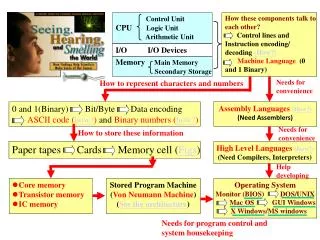
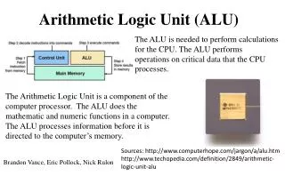
Introduction • ALU (“Arithmetic and Logic Unit”) • Responsible for certain arithmetic and logic functions. (Ex:addition,substaction,and, xor etc). • The Control Unit (“CU”) • Keep all elements of the ALU working in a harmonic way. • Different Components can be added as modules to help perform certain operations • Adder, Shifter, Delatch, etc…
Components • Adder Arithmetic functions are perform in this circuits. 1-bit adder 8-bit adder
Components • ASI Receive the operand of add, subtract and increment 1-bit adder 8-bit ASI 8-bit ASI pkg
Components • Negator Arithmetic functions are perform in this circuits. 8-bit negator 8-bit negator pkg
Components • Register Its is use for the ADC function. The rest of the functions done via the 2 buses. 8-bit register 8-bit register pkg
Components • Logic This circuit performs the logic functions and, or and all of the shifting operations. It is copied 8 times to work as an 8 bit circuit. 1-bit logic/shifter 1-bit logic/shifter pkg
Conclusion • In our design we were able to create an ALU capable of completing all of the logic and arithmetic functions specified in our simulator. • The design can be used for further continuation of a project, in which it can be used as the ALU of a microcontroller or CPU. • Our ALU might not have the fastest performance, but it has one of the simplest hardware designs.
References • Computer System Design Architecture, second ed, Vincent P. Heuring and Harry F. Jordan. • A 32-Bit ALU Design Example, http://lgjohn.ecen.ceat.okstate.edu/5253/lectures/ aludesver.pdf