Download
1 / 34
510 likes | 1.02k Views
Trane Does Controls !. Agenda. Review Controls Business Strategy Summary of Capabilities and Product Offerings. Controls Business Strategy Summary. Restore and Modernize. Controls & Service: The Platforms for Connecting Buildings to Business Results. Strategic Solutions. Systems

E N D
Agenda • Review Controls Business Strategy • Summary of Capabilities and Product Offerings
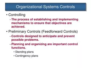
Restore and Modernize Controls & Service: The Platforms for Connecting Buildings to Business Results Strategic Solutions Systems Solutions Design and Construction Enhance Building Results Customer’s Mission Services Solutions Supply Solutions Operate, Maintain and Sustain
Account Manager • Deliver on-time • Lower stress • Right system • Increased efficiency • Understanding challenges / needs • Helping them be more competitive Contractor; Engineer Day 1 Fulfillment / Techs Equipment System Controls The Owner ($$$) HVAC Controls Strategic Sales Facilities Director Service Sales Day 2 Supply Sales
Account Manager • Deliver on-time • Lower stress • Right system • Increased efficiency • Understanding challenges / needs • Helping them be more competitive Contractor; Engineer Day 1 Fulfillment / Techs Equipment Controls Bridge the GAP System Controls The Owner ($$$) HVAC Controls Strategic Sales Facilities Director • Serve the owner’s Business’ Mission: • Customer’s customer • Customer’s associates • Customer’s business Turnkey Service Sales Day 2 Intelligent Services Parts Supply Sales CCS
Training & Support • Trane College of Building Automation - state of the art controls training in St. Paul, Minnesota • Hands on training for facility owners, operators, engineers and contractors • Local & regional training • the same courses and material taught and used in St. Paul • Great local support backed by experts in St. Paul • Tracer Summit User’s Group Quarterly
Engineering Support • Trane Site for Engineers - www.traneengineer.com • Popular System Configurations (aka PPS) • Trane BIM • TRACE Software, analysis tools, design tools, selection tools
Standard HVAC Control Applications • Chiller Plant Control • Chiller Tower Optimization • Pump Pressure Optimization • Ventilation System Optimization • VAV Fan Pressure Optimization • Demand Control Ventilation (CO2 Monitoring) • Water Source Heat Pump Loop Control
Standard, Repeatable System Applications 2.0 2.5 1.0 0.1 75 65 15 Standard Tracer Application screen Defobj VAV[boxes], // array of vav box objects (array size = boxes) setpoint // object used to store the calculated setpt Defflt maxpos, // the maximum air valve position staticsp, // calculation of the static pressure setpoint increment = 0.1, // amount by which the the setpoint may be changed high_limit = 95.0, // adjust setpoint up if max greater than this value low_limit = 85.0, // adjust setpoint down if max less than this value initial_staticsp = 2.0, // initial static pressure setpoint min_staticsp = 0.5, // minimum static pressure setpoint allowed max_staticsp = 3.0 // maximum static pressure setpoint allowed // define the property (from the database) that confirms that the // AHU is running. // IMPORTANT! Use the Add Obj&Property selection under the Edit menu // to select the correct property. ahu_status = {RTU-3 Engineering}.{Supply Fan Status} // define the AOP object (from the database) for the vav boxes served // by a particular air handling unit. This AOP should be referenced // by the ahu as its static pressure setpoint // IMPORTANT! Use the Add Object selection under the Edit menu // to select the correct objects. setpoint = {RTU-3 Static Pressure Setpt} // load the object array with the VAV objects VAV[1] = {VAV 3-01 Engineering} VAV[2] = {VAV 3-02 South America Conf. Rm} VAV[3] = {VAV 3-03 Engineering} VAV[4] = {VAV 3-04 Engineering} VAV[5] = {VAV 3-05 Engineering} VAV[6] = {VAV 3-06 Engineering} VAV[7] = {VAV 3-07 Engineering} VAV[8] = {VAV 3-08 Engineering} VAV[9] = {VAV 3-09 Test Room} VAV[10] = {VAV 3-10 Hardware Lab} VAV[11] = {VAV 3-11 Order Fulfillment} VAV[12] = {VAV 3-12 Order Fulfillment} VAV[13] = {FP VAV 3-01 Engineering} VAV[14] = {FP VAV 3-02 Engineering} VAV[15] = {FP VAV 3-03 Asia Conf. Room} VAV[16] = {FP VAV 3-04 Order Fulfillment} VAV[17] = {FP VAV 3-05 Corridor} VAV[18] = {FP VAV 3-06 Corridor} PROGRAM VAV_Critical_Zone_Reset_RTU_3 // Written: // Modified: 03/98 // Properties Read: VAV[i].{Communication State} // VAV[i].{Diag: Flow Sensor Fail} // VAV[i].{Control Mode} // VAV[i].{Air Valve Position} // VAV[i].{Communication Address} // Properties Modified: setpoint.{Present Value} // Routine Summary: /// This routine calculates the static pressure setpoint for an air /// handling unit. It resets the AHU static pressure setpoint based on /// a "critical zone". VAV terminal units' maximum air valve position /// is determined, which is the basis for calculating an AHU static pressure /// setpoint. The AHU static pressure setpoint is adjusted to satisfy /// the critical zone, which inherently satisfies all other zones. // Fan horsepower is minimized and comfort in all spaces is maintained. // For background information about this routine, see SYS-EB-2. // This cpl object, the AHU object and all (or the majority of) the VAV // objects should reside in the same BCU. (Do not put this cpl object in // one BCU if the VAV boxes and AHU reside in another BCU.) /// Routine Execution: This program is executed every 1 minute. // Note: this routine executes every minute but the reset calculation is // done only at a user defined interval (usually much less frequently). /// Routine Text File: VAV_CZR3.CPL // ***** Define Variables ***** // In this section, the programmer defines the variables used throughout // this routine. The only variables that require editing are in the "User // Edited Variables" section. No other changes are required. Defint On = 1, // define enumeration Up = 1, // define enumeration Normal = 0, // define enumeration Occupy = 0, // define enumeration for VAV control mode i, // index used in the For-Next loop ahu_status, // status feedback from AHU ahu_timer, // number of minutes since the ahu started // ***** begin User Edited Variables ***** startup_delay = 30, // number of minutes after the ahu starts before // allowing the reset to occur reset_interval = 15, // number of minutes between reset calculations // Reset Interval will depend on actual system dynamics. // Tuning the reset interval should be done with // the system operating. boxes = 18 // number of vav boxes included in the calculation Local.{Saved Value}[1] = Local.{Saved Value}[1] + 1 Stop End If Local.{Saved Value}[3] = maxpos // ***** adjust setpoint ***** // If the maximum air valve position is greater than the high limit the static // pressure setpoint is increased. If it is less than the low limit the setpoint // is decreased. The setpoint is adjusted only if the air handling unit is On and // the maximum air valve position is nonzero. It will be zero if all boxes // are not communicating or if all the flow sensors have failed. It will also // be zero if all boxes are unoccupied, (with unocc min allowed to go to zero). // The setpoint will be set to the user defined initial setpoint if the adjustment // calculation is not done. After the setpoint is calculated, it is verified that // it does not exceed its minimum or maximum. // No changes are required in this section. staticsp = setpoint.{Present Value} If (maxpos <> 0.0) Then If (maxpos > high_limit) Then staticsp = (staticsp + increment) End If If (maxpos < low_limit) Then staticsp = (staticsp - increment) End If Else staticsp = initial_staticsp End If staticsp = Min (staticsp, max_staticsp) staticsp = Max (staticsp, min_staticsp) // ***** control AOP ***** // Control the analog output to the calculated static pressure // setpoint only if it has changed. // No changes are required in this section. If (setpoint.{Present Value} <> staticsp) Then CONTROL(setpoint,{Present Value},staticsp,16,Set) End If End // end of routine // ***** end User Edited Variables ***** // No changes are required beyond this point. // ***** ahu timer ***** // In this section a counter keeps the number of minutes the ahu // status shows the unit has been On. The counter is stored in // Local.{Saved Value}[16]. If the ahu status is Off the counter is // reset to 0 and the setpoint is reset to its user defined initial // value. The routine also stops if the ahu status is Off; there is // no reason to run the rest of the routine with the ahu Off. This // counter is used to verify the ahu has been On a user defined // number of minutes before allowing the static pressure to be // adjusted. ahu_timer = Local.{Saved Value}[16] If (ahu_status = On) Then ahu_timer = ahu_timer + 1 Else Local.{Saved Value}[16] = 0 If (setpoint.{Present Value} <> initial_staticsp) Then CONTROL(setpoint,{Present Value},initial_staticsp,16,Set) End If Stop End If Local.{Saved Value}[16] = ahu_timer // ***** vav box data ***** // In this section the air valve position is read from each vav box that // is communicating with the bcu and has a valid air flow reading. A // failed flow results in air valve position based control. This strategy // requires "pressure independent" flow control. The vav UCMs must be // in occupied mode and communicating with the bcu to properly read // values and perform calculations. This for-next loop finds the position // of the most open VAV box air valve. The routine will only find the // most open box after the ahu has gone through its user defined startup // delay. It only performs the rest of the routine every user interval, not // every minute. // No changes are required in this section. If (Local.{Saved Value}[1] >= reset_interval) and (ahu_timer > startup_delay) Then Local.{Saved Value}[1] = 0 Local.{Saved Value}[2] = 0 For i = 1 To boxes Step 1 If (VAV[i].{Communication State} = Up) and (VAV[i].{Diag: Flow Sensor Fail} = Normal) and (VAV[i].{Control Mode} = Occupy) Then If (VAV[i].{Air Valve Position} > maxpos) Then maxpos = VAV[i].{Air Valve Position} Local.{Saved Value}[2] = VAV[i].{Communication Address} End If End If Next Else Typical method Repeatable - performance from building to building and job to job
Tracer Chiller Plant Control • Repeatability – Performance from plant to plant • Maximize the use of pre-engineered features • Minimize on-site customization • Flexibility • Supports a variety of plant layouts • Supports a variety of chiller types • Supports a variety of control strategies • Maximize Energy Savings • Minimize manual intervention • Thermal Ice Storage • Chiller Tower Optimization • Distributed pump pressure optimization • Load matching • Minimize Operational Costs • Minimize manual intervention, but anticipate it • Maintain chilled water flow and temperature • Minimize service surprises
Tracer Products Enterprise Tracer ES Tracer SC Tracer BCU Building Tracer UC Lontalk Equipment Tools and Services Spaces Sensors
Tracer™ Architecture Firewall Tracer ES BACnet Ethernet LAN Tracer SC Building Control BuildingControl Internet/Intranet ProgrammableController AdaptiView & UC 800 ProgrammableController Field-applied Controller Air Handlers Chillers VAV
HVAC Equipment Factory Control Options * Terminal Strip – Field Mount ** Phase 1 – BC in 2H2011 Broad coverage for both LonTalk and BACnet
Tracer Summit™Building Control Unit (BCU) • Supports all Trane equipment • System integration platform (LON, BACnet) • Modular, expandable • Standard and programmable control sequences • Modem and Ethernet/IP network access from PC
Value to Customer System applications, pre-engineered Easy web-enabled access Improved user interface Key Features Web-based interface Scalability Smaller incremental steps to build up a system Open standard protocol support (and integration point) BACnetTM and LonTalkTM Delivery platform for engineered system applications Air systems and central plant control Building ControlTracer SC…Linking Trane systems to the Web
Value to Customer Improved operating productivity Web access Integration with other systems Key Features Easy-to-use customer interface for daily building operations Web-based, remote access Multiple building scheduling and control Historical data collection and analysis System Integration platform for non-Trane BACnetTM systems Enterprise ControlTracer ES…Managing Multiple Buildings
Tracer ES – Supported Systems Tracer ES – Supported Systems Tracer ES Remote PC Internet BACnet/IP ALC LonWorks TP/FT-10 Lighting Panel BACnet MS/TP JCI Trane Unit Controls Tracer SC Summit BCU Tracker BACnet Systems
Additional Solutions Reporting Tools Integration Tools Intelligent Services
BACnet LonTalk Comm 3 Comm 4 LonTalk Integration Capabilities Tracer ES BACnet/IP JENEsysIntegration ALC Tracer SC JCI Modbus Siemens JCI Tracer BCU Honeywell Lighting Panel Lighting • Non-TraneLonTalk Devices • Non-TraneBACnet/MSTP Devices Security Other • Non-Trane BACnet/IP • Legacy Trane Protocols • Non-Trane LonTalk Devices • Non-Trane Protocols Other than BACnet Every job requires some level of integration… …and Trane has solutions for each level
Trane Intelligent Services operate 24 hours, 7 days a week and acts as a technical partner to your local Trane Service provider. We proactively and continuously identify operational and environmental issues from Ipak, Voyager, and Precedent equipment. This allows us to: Identify and correct problematic behavior immediately – night, day, over seasonal changes, permitting the customer to maintain a high level of efficiency in their building. Reduces energy consumption and enables cost avoidance. Reports demonstrate building performance and opportunities for system optimization Trane Intelligent Services (TIS)
Why Trane? • Better comfort • Lower energy usage • Better Indoor Air Quality (IAQ) • Quieter operation • More reliable • Faster commissioning • Easier to maintain • Lower total operating costs • Extends the life of assets